
Description
Hard-Numbers: Technical Specifications
-
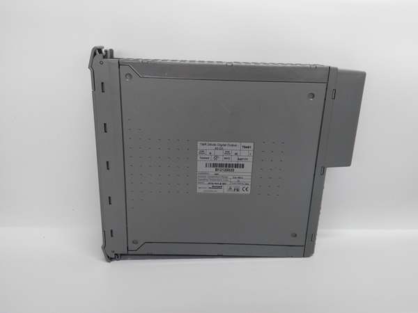
Output Channels: 40 TMR digital outputs (triplicated circuits per channel)
-
Power Grouping: 5 independent groups of 8 outputs each (each group has common supply/return)
-
System Supply Voltage: 20 to 32V DC
-
Field Voltage Range: 18 to 32V DC (operational); 0 to 36V DC (measurement)
-
Maximum Withstanding: -1 to 40V DC (surge); -1 to 60V DC (some specs)
-
Output Current: 2A per channel continuous; 8A max per power group
-
Minimum Load Current: 50 mA (on-state)
-
Output On Resistance: 0.6 Ω
-
Output Off Resistance (Leakage): 33 Ω (effective)
-
Isolation: ±250V DC sustained working; ±2.5 kV DC maximum impulse withstand
-
Output Delay: 0.5 ms turn-on/turn-off
-
Sample Update Time: 0.5 ms
-
Sequence of Events (SOE): 1 ms resolution
-
Self-Test Interval: 2 minutes (automatic internal test)
-
Short Circuit Protection: Electronic latching (automatic, no fuses required)
-
Power Consumption: 24W field supply (1A per channel); 24W system supply @ 24V
-
Operating Temperature: -5°C to +60°C (standard); -20°C to +60°C (some variants)
-
Storage Temperature: -25°C to +70°C
-
Humidity: 5% to 95% RH non-condensing
-
Dimensions: 300 mm × 30 mm × 241 mm (L × W × H) / 30cm × 3cm × 24.1cm
-
Weight: 1.13 kg (2.5 lbs); 3 kg shipping weight
-
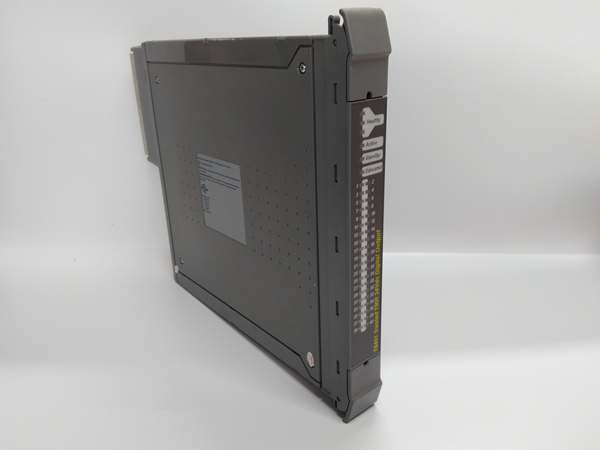
Hot Swap: Yes (Companion Slot or SmartSlot configuration)
-
Certifications: TÜV SIL 3 (IEC 61508), CE, ATEX

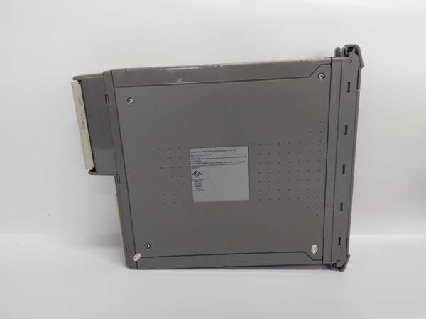
ICS TRIPLEX T8451
The Real-World Problem It Solves
Safety instrumented systems need to drive final control elements—shutdown valves, motor starters, burner fuel valves—without the risk of a single component failure causing a spurious trip or failing to operate on demand. Traditional single-channel outputs provide no diagnostic coverage; a shorted driver or welded contact goes undetected until the safety function is required. The T8451 puts three independent output circuits on every channel, voting the results in real-time. If one driver fails shorted or open, the other two maintain safe operation while the module flags the fault for repair.
Where you’ll typically find it:
-
Emergency shutdown (ESD) valve solenoids on oil & gas platforms
-
Burner management fuel valve controls in power plant boilers
-
Fire & gas deluge valve drivers in chemical processing units
This module eliminates the “single point of failure” in safety output loops while providing 1ms event recording for post-trip analysis and automatic short circuit protection that eliminates external fusing.
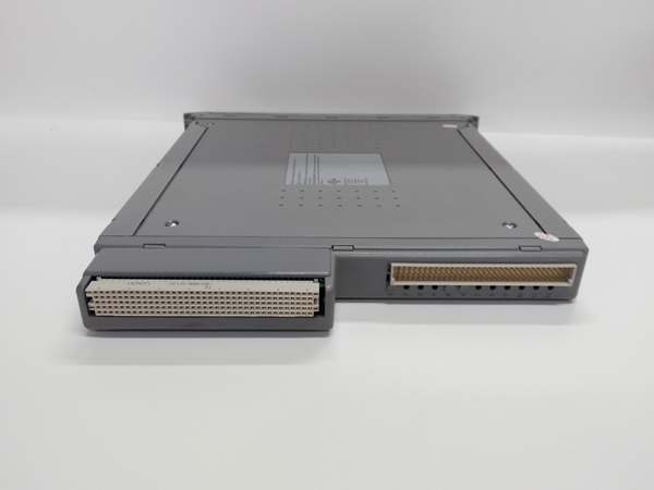
Hardware Architecture & Under-the-Hood Logic
The T8451 functions as a safety-critical output driver—not merely switching loads, but monitoring current, voltage, and circuit health with three independent channels voting on every output state.
Signal flow and processing logic:
-
Triplicated Outputs: Each of the 40 channels drives three independent output switches (A, B, C). Each switch has its own driver circuit, current monitoring, and diagnostic feedback.
-
2oo3 Voting: A dedicated voter circuit compares the commanded state from the TMR Processor with the actual output of each switch. If two switches agree on the state, that state drives the field device. If one disagrees, it’s masked and flagged.
-
Current Monitoring: Each output circuit measures load current independently. The module detects open circuits (broken wires, failed solenoids) and short circuits (field wiring faults) by comparing expected vs. actual current draw.
-
Electronic Protection: On overcurrent detection, the module latches the affected channel off electronically—no fuses to replace. The fault is reported to the TMR Processor via the IMB (Inter-Module Bus).
-
Line Monitoring: When enabled, the module performs dynamic line monitoring to detect field wiring faults without disturbing the output state. This catches degraded wiring before it causes a failure.
-
Power Grouping: Outputs are organized into 5 groups of 8, each with independent power and return paths. This isolates faults to a group rather than the entire module.
-
SOE Recording: A 1ms-resolution timestamp latches on any output state change, regardless of scan rate, for sequence reconstruction during incident analysis.
ICS TRIPLEX T8451
Field Service Pitfalls: What Rookies Get Wrong
Ignoring the Minimum Load Current
The T8451 requires a minimum 50mA load current to maintain the on-state. With high-impedance loads or long cable runs with capacitive leakage, the output may chatter or fail to stay energized—looking like a module fault when it’s really a load problem.
-
Field Rule: Verify load impedance before installation. For low-current loads (pilot lights, high-impedance solenoids), add a bleeder resistor across the output to draw at least 50mA. Document this in the I/O list—future techs will assume the module is defective if they don’t know about the minimum load requirement.
Mixing Power Groups
Each group of 8 outputs shares a common power feed and return. If you wire a critical ESD valve and a non-critical indicator light to the same group, a short on the indicator can take down the entire group—including your safety valve.
-
Quick Fix: Group outputs by criticality and function. Put all ESD valves in one group, all fire & gas outputs in another. Never mix safety and non-safety loads on the same power group. Check the group current total; if you’re running 8 channels at 2A each, you’re at the 8A group limit—any inrush current will fault the group.
Assuming “Electronic Protection” Means Indestructible
The electronic short circuit protection latches the channel off on overcurrent, but it doesn’t protect against sustained overvoltage. If field wiring faults apply >40V to the output terminals, the protection circuitry itself can be damaged.
-
Field Rule: The -1 to 40V withstand rating is for transients, not continuous overvoltage. If you suspect field wiring damage (lightning strike, cable crush), measure the field voltage before reconnecting the T8451. A sustained 48V from a failed power supply will destroy the output drivers despite the “protection.” Always verify field wiring insulation resistance with a megger after any cable damage event.


