
Description
Hard-Numbers: Technical Specifications
- Channel Count: 8 universal channels (individually configurable as DI/DO/AI/AO)
- Signal Types Supported:
- Digital: 24VDC, contact input, NAMUR, 2-wire transmitter
- Analog: 4–20 mA, 0–10V, 0–20 mA
- Redundancy: Dual redundant processing paths (Chain A / Chain B)
- Diagnostic Coverage: >99% per IEC 61508 (SIL 3)
- Response Time: Digital inputs <10 ms; Digital outputs <5 ms
- Update Rate: 10–100 ms configurable (Safety Manager scan rate dependent)
- Isolation Rating: Channel-to-bus: 1500VAC; Channel-to-channel: 500VAC typical
- Operating Temperature: -20°C to +60°C full load; -40°C to +70°C derated
- Storage Temperature: -40°C to +85°C
- Humidity: 10–90% RH non-condensing
- Power Consumption: 5–8W typical (varies with channel configuration and load)
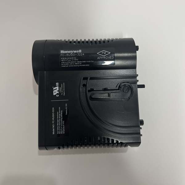
- Certifications: TÜV SIL 3 per IEC 61508, IEC 61511; UL/cUL Class I Div 2; CE; ATEX (varies by revision)
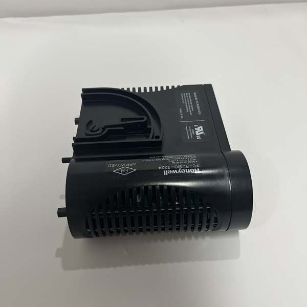
- Dimensions: 191 mm × 188 mm × 65 mm (7.5″ × 7.4″ × 2.6″)
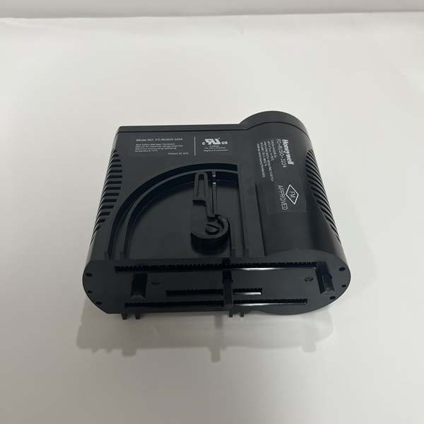
- Mounting: Hot-swappable in Safety Manager I/O chassis
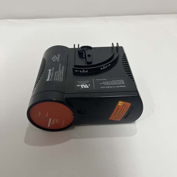
Honeywell FC-RUSIO-3224
The Real-World Problem It Solves
Safety systems can’t afford single points of failure, and stocking four different I/O module types (AI, AO, DI, DO) burns budget and cabinet space. When a Safety Manager system needs mixed signals—discrete valve feedback from limit switches, 4–20 mA pressure transmitters, analog outputs to valve positioners—you either run multiple specialized modules or risk using non-redundant I/O in a SIL 3 application. The FC-RUSIO-3224 gives you 8 universal channels in a single redundant package, handling any signal type while maintaining full SIL 3 integrity.
Where you’ll typically find it:
- Safety Manager ESD cabinets with mixed I/O requirements—valve position feedback (DI), process monitoring (AI), and solenoid outputs (DO) on the same module
- HIPPS (High-Integrity Protection Systems) requiring redundant valve position feedback and analog pressure monitoring
- Fire & gas systems combining discrete detector inputs with analog flame detector 4–20 mA signals
Bottom line: One module does the work of four, with redundancy baked in—no single-point failure, no spares nightmare.
Hardware Architecture & Under-the-Hood Logic
The FC-RUSIO-3224 is a redundant universal I/O module designed for the Honeywell Safety Manager backplane. It slides into the I/O chassis and communicates via dual redundant Fieldbus connections to the Safety Manager controller. Inside, two independent microcontroller-based processing chains (A and B) operate in parallel for SIL 3 compliance. Each of the 8 channels has a reconfigurable analog front-end that switches between digital input, digital output, analog input, or analog output mode—all software-configurable, no jumpers required.
-
Signal Conditioning Front-End: Each channel starts with a software-switchable signal conditioning stage that adapts to the configured signal type. Digital inputs get 24VDC wetting voltage and debounce filtering; analog inputs receive precision 4–20 mA / 0–10V scaling and 24-bit ADC conversion; outputs get DAC and drive circuitry. No hardware changes—just database parameters.
-
Dual Redundant Processing Paths: Both Chain A and Chain B independently process every channel’s signal simultaneously. The two chains compare results via internal cross-checking logic. If Chain A reads “ON” and Chain B reads “OFF” or their analog values diverge beyond tolerance, a fault is flagged immediately. This lockstep comparison provides the >99% diagnostic coverage required for SIL 3.
-
Redundant Fieldbus Interface: Two separate fieldbus connections (Fieldbus A and Fieldbus B) link the module to the Safety Manager controller. Each processing chain communicates via its dedicated interface. If one fieldbus path fails or loses communication, the other path maintains full safety function. The controller continuously monitors both paths and alarms on divergence.
-
Hot-Swap Logic: In redundant configurations, one FC-RUSIO-3224 can be physically removed while the system stays online. The surviving processing chain maintains safety function during the swap. When the new module is inserted, it automatically syncs configuration and state with the partner module. The Safety Manager controller handles switchover without operator intervention.
-
Diagnostic Engine: The module continuously runs internal diagnostics—watchdog timers, memory checksums, power supply monitoring, temperature sensing, channel wire-break detection, short-circuit detection, and out-of-range checks. Faults are immediately reported to the controller via redundant fieldbus. The controller then takes predefined action: force outputs to safe state, alarm operators, or bypass failed channels while keeping healthy ones running.
Honeywell FC-RUSIO-3224
Field Service Pitfalls: What Rookies Get Wrong
Assuming Universal Channels Mean “Mix Anything Randomly”
New engineers see “universal channels” and start wiring critical ESD valve feedback next to non-critical monitoring transmitters on the same module. When that module fails for any reason, both safety and monitoring functions drop together. You lose redundancy by packing critical and non-critical signals on a single card, defeating the purpose of separation.
- Field Rule: Group safety-critical and non-safety signals across separate modules where possible. If they must share a module, ensure Safety Manager logic handles module-level failures gracefully (degraded operation vs. full shutdown). Never assume “universal” means “no planning needed.”
Plugging Both Redundant Fieldbuses into the Same Switch
I’ve seen techs run both Fieldbus A and Fieldbus B cables to the same network switch or daisy-chain them through a single device. If that switch fails, both redundant paths go dead simultaneously—the module loses communication with the controller and forces the safety function to failsafe state. The redundancy is an illusion when the physical network isn’t truly independent.
- Quick Fix: Verify that Fieldbus A and Fieldbus B are on physically separate network paths with independent switches or media. Test live failover: pull Fieldbus A while monitoring the Safety Manager diagnostics to confirm Fieldbus B maintains communication without faults. Don’t trust redundancy until you’ve seen it survive a real failure.
Missing Analog Range Verification After Replacement
When swapping a failed FC-RUSIO-3224, techs sometimes upload configuration from the controller without verifying analog range settings. The old module might have been calibrated for 4–20 mA, but the replacement defaults to 0–10V. The Safety Manager reads scaled values incorrectly, logic decisions get corrupted, and you either get spurious trips or fail to trip when you should.
- Field Rule: After module replacement, always verify channel configuration against loop sheets and Safety Manager project documentation. Use a calibration source (Fluke 744 or equivalent) to inject known signals and confirm the controller reads expected values. Document any calibration offsets. Don’t assume “same part number = same configuration.”
Grounding All Shields at Both Ends
This module handles both analog and digital signals in the same cable bundle. Rookies terminate all shields at both the field device and the cabinet, creating ground loops that inject noise into 4–20 mA analog signals. Readings bounce, out-of-range alarms fire, and in worst cases, safety function performance degrades undetected.
- Field Rule: Follow Honeywell grounding guidelines: terminate analog signal shields at the field device end only (single-point grounding), or at the cabinet end only if the field device is already grounded. Never ground shields at both ends unless using shielded twisted pair specifically designed for that configuration. Keep analog and digital cables separate where possible.
Never Testing Redundant Switchover
Techs install redundant FC-RUSIO-3224 modules, configure them, and assume redundancy works because both show “ONLINE.” When a real failure occurs months later, switchover doesn’t happen—modules were in active-passive mode, or the secondary wasn’t fully synced. The safety function goes offline when it should have survived.
- Quick Fix: Perform a controlled failover test during commissioning or scheduled outage: power down the primary module and verify the secondary maintains all channel states without spurious alarms. Document failover time and any transient faults. Test annually or after any configuration changes. Don’t trust redundancy until you’ve proven it works under load.
Commercial Availability & Pricing Note
Please note: The listed price is for reference only and is not binding. Final pricing and terms are subject to negotiation based on current market conditions and availability.


