
Description
Hard Numbers: Technical Specifications
- Input Voltage Range: 88 V DC to 264 V DC (Typical 125V/250V DC substation battery)
- Output Voltage: 24 V DC (Regulated)
- Output Current: 10 A (240 W Continuous Power)
- Output Ripple: < 50mVpp (Typical)
- Isolation Rating: 1500 V AC (Input to Output), 500 V AC (Output to Chassis)
- Efficiency: > 88% at Full Load
- Operating Temperature: -40°C to +70°C (-40°F to +158°F)
- Protection Features: Overvoltage, Overcurrent, Short Circuit, and Overtemperature Protection
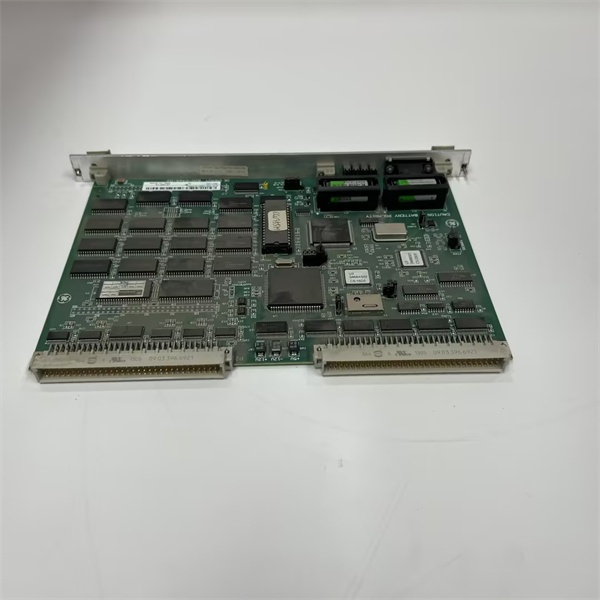
GE WESDAC D20M
The Real-World Problem It Solves
Substation voltage is notoriously dirty. Between the massive inrush currents of switching operations and the occasional lightning strike, your standard commercial power supply will shut down or let dangerous transients fry your sensitive RTU electronics. The WESDAC is built to take the punishment of heavy industrial electrical environments. It scrubs the dirty station battery power clean, delivering a perfectly regulated 24V DC to your D20 backplane.
Where you’ll typically find it:
- Bolted into the power slot of a D20/D200 RTU rack in a high-voltage transmission substation.
- Providing isolated 24V DC to I/O modules and communication cards in power generation plants.
- Serving as a redundant power source (1+1 or N+1) in critical infrastructure where a power supply failure means losing SCADA visibility.
It eliminates the need for external isolation transformers and bulky line conditioners, packing robust surge suppression and tight voltage regulation into a single rack-mounted unit.
Hardware Architecture & Under-the-Hood Logic
This isn’t a simple linear regulator; it’s a switch-mode power supply designed for continuous operation in electromagnetically hostile environments.
- Input Filtering & Surge Suppression: The module starts with massive EMI/RFI filtering and metal oxide varistors (MOVs) to clamp voltage spikes from lightning or switching transients before they reach the main circuitry.
- Active Power Factor Correction (PFC) & Switching: The AC/DC converter actively shapes the input current waveform to maximize power efficiency and minimize harmonic distortion on the station battery.
- DC-DC Conversion & Regulation: A high-frequency transformer provides galvanic isolation between the input mains and the 24V DC output. A pulse-width modulation (PWM) controller constantly adjusts the duty cycle to maintain a rock-solid 24V output, regardless of input fluctuations or sudden load changes.
- Diode-ORing for Redundancy: The output stage includes robust Schottky diodes for parallel operation. You can slap two modules in the same rack, and if one dies, the other seamlessly picks up the load without dropping the 24V rail.
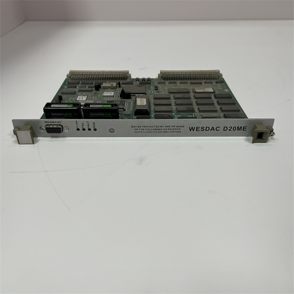
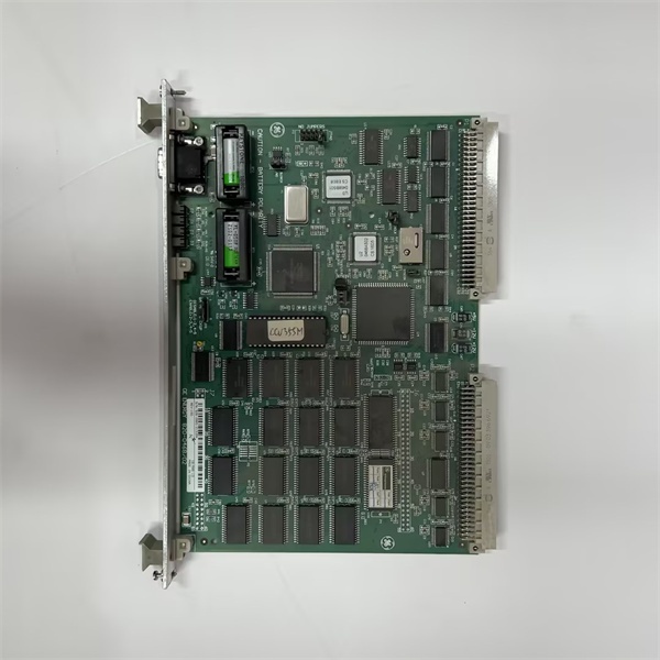
GE WESDAC D20M
Field Service Pitfalls: What Rookies Get Wrong
Improper Redundant Wiring (Reverse Polarity)
Rookies installing a second for redundancy often rush the wiring. They accidentally swap the positive and negative terminals on the secondary unit. When they energize the system, the reverse-biased diodes prevent the units from sharing the load, or worse, they create a dead short that trips the station battery breaker.
- Field Rule: Before closing the breaker, always use a multimeter to check the output polarity of the power supply andverify the voltage at the RTU backplane. Ensure the diode-ORing jumpers on the D20 backplane are correctly configured for redundant power supplies.
Ignoring the DC OK Signal
When the starts to fail, it usually gives a warning via the “DC OK” relay contact. Rookies ignore this tiny dry contact or fail to wire it into the system alarm inputs. They miss the early warning signs until the unit completely dies, taking the RTU offline.
- Quick Fix: Always wire the “DC OK” contact to a spare digital input on the RTU or a central alarm panel. If you see the “DC OK” light flickering or the alarm triggering intermittently, the output capacitors are likely drying out, and it’s time to swap the unit beforeit fails catastrophically.
Forgetting to Tighten the Line-Terminal Screws
The sits in a cabinet that sees constant vibration from nearby transformers, cooling fans, or heavy machinery. Rookies use a standard screwdriver to tighten the 125V/250V input terminals. Over time, thermal cycling and vibration loosen the connections, leading to a high-resistance joint that eventually arcs or causes an intermittent power loss to the RTU.
- Field Rule: Use a proper torque screwdriver. Tighten the power terminals to the manufacturer’s specified torque (usually around 7-9 in-lbs). Apply a dab of vibration-resistant threadlocker fluid to the screws if the cabinet is in a high-vibration area.
Commercial Availability & Pricing Note
Please note: The listed price is for reference only and is not binding. Final pricing and terms are subject to negotiation based on current market conditions and availability.


