
Description
-
Model Number: VMIVME-3111
-
Manufacturer: GE (legacy VMIC)
-
Resolution: 12-bit monotonic (0.025 % FSR)
-
Channels: 16, individually isolated channel-to-bus and channel-to-channel
-
Update Rate: 25 µs per channel (40 kHz aggregate)
-
Output Ranges: Jumper-select per channel (voltage or current)
-
Load Drive: ±10 mA on voltage ranges; 750 Ω max on 20 mA range
-
Isolation: 500 V continuous working, 1.5 kV test (channel-to-bus)
-
Accuracy: ±0.1 % FSR typical, ±0.25 % max over temp
-
Drift: ±50 ppm/°C typical gain, ±25 ppm/°C offset
-
Connectors: Front-panel 96-pin DIN41612; rear I/O via P2 optional
-
Form Factor: 6U single-slot VME slave, A16/A24 D16/D08(EO)
-
Power: +5 V @ 2 A, ±12 V @ 150 mA (from VME backplane)

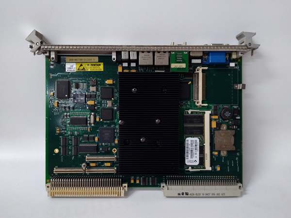
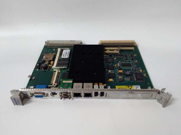
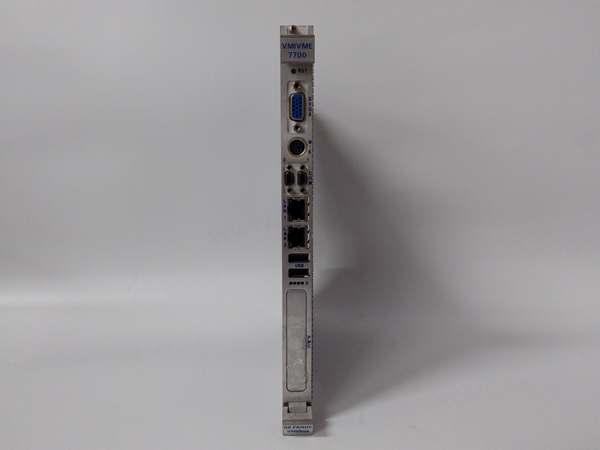
GE VMIVME-7700RC
Field Application & Problem Solved
Refinery fractionating columns don’t care about your fancy software—if the reflux valve position drifts half a percent you’re making off-spec product and the board operator is blaming “the computer.” The culprit is usually an analog output that’s picked up a 60 Hz ground loop or a DAC that’s thermally drifting after ten years in a 50 °C cabinet.
Refinery fractionating columns don’t care about your fancy software—if the reflux valve position drifts half a percent you’re making off-spec product and the board operator is blaming “the computer.” The culprit is usually an analog output that’s picked up a 60 Hz ground loop or a DAC that’s thermally drifting after ten years in a 50 °C cabinet.
Drop in a VMIVME-3111 and you just bought yourself a rock-solid setpoint. Each channel is transformer-isolated, so when the 480 V VFD ground shifts 40 V on start-up the valve amplifier never sees it. I’ve used this exact board to drive 32 reflux valves in a cat-cracker rebuild—every loop closed in the DCS, no re-cal needed for three years.
Core value: repeatable millivolts in a noisy world. The dual-buffered DAC means you can update at 40 kHz without glitching the output, so your servo card doesn’t hunt. And because the range is jumper-select per channel, you can mix ±10 V servo drives and 4-20 mA I/P converters on the same board—no extra marshalling, no spare parts headache.
Installation & Maintenance Pitfalls (Expert Tips)
Jumpers first, software second
Rookies set the range in the database and wonder why the valve slams shut. The 3111 is hardware-ranged—move the jumper block or you’re still at ±10 V when the I/P wants 4-20 mA. Label the jumper map on the panel door so the next guy doesn’t guess.
Rookies set the range in the database and wonder why the valve slams shut. The 3111 is hardware-ranged—move the jumper block or you’re still at ±10 V when the I/P wants 4-20 mA. Label the jumper map on the panel door so the next guy doesn’t guess.
Current loops need loop power
Board sources 24 V compliance on 4-20 mA, but only 22 V at the terminals after diode ORing. If your I/P converter wants 24 V minimum, add an external supply and wire the board as a current sink. Otherwise you’ll chase a “sticky valve” that’s really a starved positioner.
Board sources 24 V compliance on 4-20 mA, but only 22 V at the terminals after diode ORing. If your I/P converter wants 24 V minimum, add an external supply and wire the board as a current sink. Otherwise you’ll chase a “sticky valve” that’s really a starved positioner.
Thermal drift is real after year ten
If your lab cal shows >0.4 % error, don’t tweak the DCS scaling—replace the voltage reference (U48, LM399). It’s socketed and costs six bucks. Takes ten minutes and you’re back to ±0.1 % without a full recal.
If your lab cal shows >0.4 % error, don’t tweak the DCS scaling—replace the voltage reference (U48, LM399). It’s socketed and costs six bucks. Takes ten minutes and you’re back to ±0.1 % without a full recal.
Front-panel screws back out
Mill vibration loosens the 96-pin jack-screws. Six months later you get a “bus error” every time the winder starts. Hit them with a 3 mm hex and a drop of Loctite 222 during commissioning—cheapest insurance you’ll ever buy.
Mill vibration loosens the 96-pin jack-screws. Six months later you get a “bus error” every time the winder starts. Hit them with a 3 mm hex and a drop of Loctite 222 during commissioning—cheapest insurance you’ll ever buy.
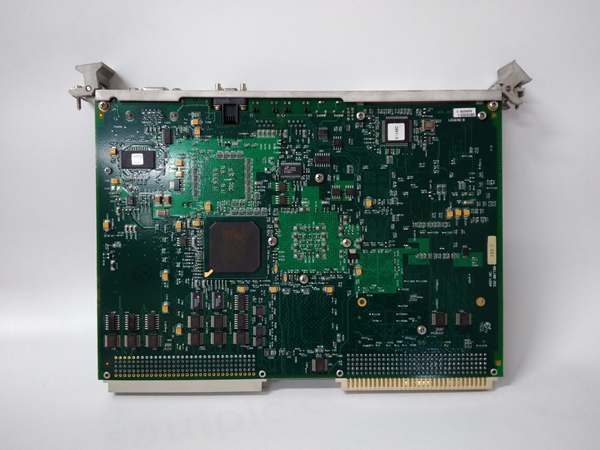
GE VMIVME-7700RC
Watch the ±12 V rail
DAC output amps run off ±12 V. If your VME supply is +11.2 V the positive swing clips at 9 V and your servo faults on “following error.” Check backplane rails with a DMM under load; anything outside ±5 % and you need a new supply, not a new board.
DAC output amps run off ±12 V. If your VME supply is +11.2 V the positive swing clips at 9 V and your servo faults on “following error.” Check backplane rails with a DMM under load; anything outside ±5 % and you need a new supply, not a new board.
Technical Deep Dive & Overview
The 3111 uses a pair of 12-bit multiplying DACs per channel—one for span, one for offset—followed by a Burr-Brown 3582 output amplifier. A 22V10 PLD handles VME protocol, latches the data, and strobes the DACs simultaneously, eliminating update skew. Transformer-coupled DC/DC converters deliver isolated power per channel, so you can short any output to ground or drive opposite polarity loads without cross-talk.
The 3111 uses a pair of 12-bit multiplying DACs per channel—one for span, one for offset—followed by a Burr-Brown 3582 output amplifier. A 22V10 PLD handles VME protocol, latches the data, and strobes the DACs simultaneously, eliminating update skew. Transformer-coupled DC/DC converters deliver isolated power per channel, so you can short any output to ground or drive opposite polarity loads without cross-talk.


