GE IS420YDOAS1B | Mark VIe Discrete Output I/O Pack – 12 Relay Field Notes

  • Model: IS420YDOAS1B
  • Alt. P/N: IS420YDOAS1A (previous gen), IS420YDOAS2B (32-ch variant), IS220YDOAS1A (Mark VIeS version)
  • Product Series: GE Mark VIe / Mark VIeS Speedtronic
  • Hardware Type: Discrete Output I/O Pack (distributed I/O module)
  • Key Feature: 12 relay outputs with individual coil monitoring, dual IONet Ethernet ports, and TMR redundancy support in a compact DIN-rail mountable package
  • Primary Field Use: Distributed discrete output control for gas/steam turbine safety systems, driving relays, solenoids, and contactors via terminal boards
In Stock
Manufacturer:

Our extensive catalogue, including , is available now for dispatch to the worldwide. Brand:

Description

Hard-Numbers: Technical Specifications

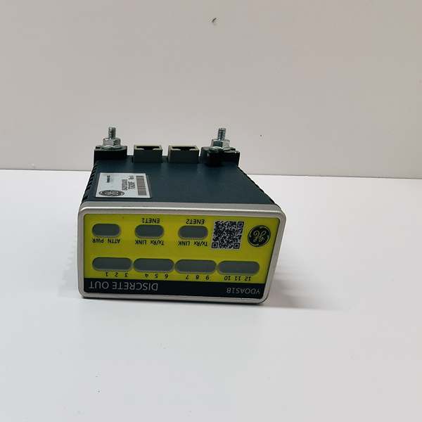
  • Output Channels: 12 relay outputs with coil/feedback monitoring

  • Output Type: Electromagnetic relays (Form-C contacts)

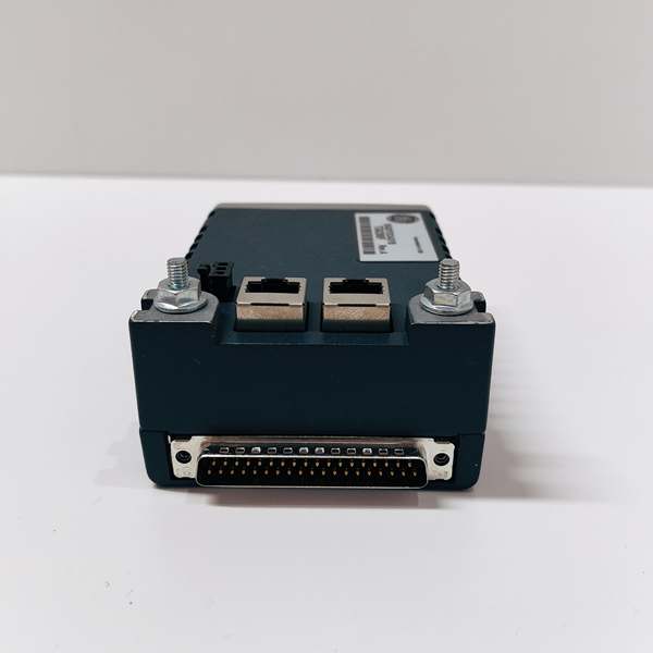
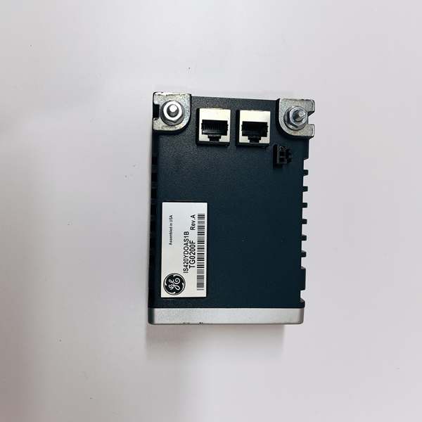
  • Communication: Dual RJ45 Ethernet (IONet, 10/100 Mbps)

  • Power Input: 3-pin connector, 24VDC nominal

  • Output Connector: DC37-pin to terminal board (SRLY, TRLY types)

  • Processor: BPPC (Backplane Processor) board with embedded logic

  • Redundancy: Simplex (1 pack) or TMR (3 packs) configurations

  • Response Time: 6 ms (typical)

  • Operating Temperature: -40°C to +70°C (-40°F to 158°F)

  • Dimensions: 3.25″ H × 1.65″ W × 4.78″ D (8.26 cm × 4.19 cm × 12.1 cm)

  • Weight: ~0.3-0.5 kg

  • LED Indicators: 12 yellow (relay status), ATTN LED (red/green, diagnostic patterns)

  • Mounting: DIN rail or panel mount

  • Certifications: IEC 61508 SIL 2 (Mark VIeS variant)

  • Compatible Terminal Boards: SRLY (Simplex Relay), TRLY (TMR Relay), TRLYS (Safety)

    GE IS420YDOAS1B

    GE IS420YDOAS1B

The Real-World Problem It Solves

You know the headache: legacy Mark VI systems with centralized I/O requiring miles of field wiring back to the main rack, or safety shutdown systems that need TMR voting but you don’t have the cabinet space for three separate output modules. The IS420YDOAS1B eliminates these constraints with distributed I/O architecture—mount the pack near the field devices, run a single Ethernet cable back to the UCS controller, and you’re done. The 12 relay outputs each have coil monitoring, so you know if a solenoid actually energized or if the relay contact welded shut. In TMR mode, three packs vote the outputs, ensuring a single hardware fault can’t cause a spurious trip or fail to operate when needed.
Where you’ll typically find it:
  • Mark VIe distributed I/O nodes controlling fuel shutoff valves and lube oil pumps in gas turbine enclosures
  • Safety instrumented systems (SIS) for emergency shutdown valves in LNG export facilities
  • Wind turbine pitch control systems requiring SIL-rated relay outputs
Bottom line: It brings TMR-capable, safety-certified discrete outputs to the field via Ethernet, eliminating wiring runs and providing diagnostic visibility that traditional relay panels can’t match.

GE IS420YDOAS1B

GE IS420YDOAS1B

Hardware Architecture & Under-the-Hood Logic

The IS420YDOAS1B is a distributed I/O pack, not a traditional rack-mounted module. It contains a BPPC processor board (common to all Mark VIe I/O packs) and an acquisition board specific to discrete outputs. The pack mounts on a terminal board (like SRLY or TRLY) which provides the actual relay coils and field wiring terminals. Communication to the UCS controller is via dual redundant IONet Ethernet—if one network fails, the other maintains control without interruption.
Signal flow and control logic:
  1. Command Reception: The BPPC processor receives discrete output commands from the UCS controller via IONet Ethernet at each scan cycle (~5 ms)
  2. Voting (TMR Mode): In TMR configurations, three YDOA packs receive the same command and vote; if one pack disagrees, it’s overruled by the other two (2-out-of-3 voting)
  3. Relay Drive: The acquisition board energizes the relay coils on the terminal board via the DC37 connector; each output has independent current limiting and flyback protection
  4. Feedback Monitoring: The pack monitors relay coil current and contact status (via auxiliary contacts) to verify the relay actually picked up; discrepancies trigger “Relay Failed” alarms
  5. Diagnostics: The ATTN LED flashes specific patterns—two