
Description
System Architecture & Operational Principle
The is a distributed I/O pack sitting at Level 1/2 of the Purdue Model, designed to reduce cabinet footprint by merging the functions of a PDIA (Input) and PDOA (Output) into a single unit. It connects directly to terminal boards—TDBS for Simplex applications or TDBT for Triple Modular Redundant (TMR) setups—via a DC-62 (37-pin) connector.
Upstream, it communicates with the Mark VIe controller (UCVE/UCVGH) over dual redundant IONet (Ethernet) ports (ENET A/B). The pack runs an internal processor that scans the 24 discrete inputs with a hardware debounce filter (typically 4ms fixed) to reject contact bounce and electrical noise from the turbine deck. It drives 12 low-side switches to energize the coil circuits on the attached terminal board (e.g., driving SRLY relays on a TDBS). This local processing offloads the main controller, ensuring deterministic response for critical loops like lube oil pump control or ESD valve permissives without saturating the Ethernet bandwidth.
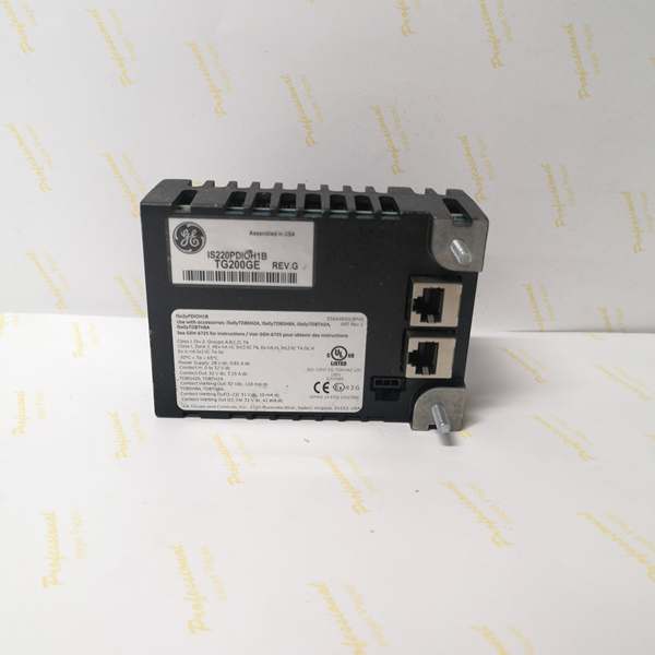
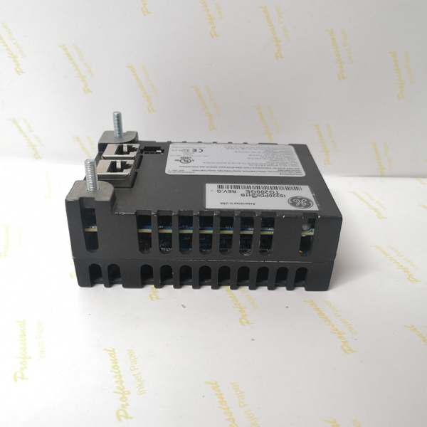
IS220PDIOH1B
Core Technical Specifications
- Input Channels: 24 (Dry/Wet Contact Sensing, Optically Isolated)
- Input Voltage Range: 18–32 V DC (Configurable via Terminal Board Jumpers)
- Input Filter: Fixed 4 ms Hardware Debounce (Non-configurable in basic modes)
- Output Channels: 12 (Form-C Relay Drivers / Low-Side Switches)
- Output Capability: Sinking 24 V DC @ ~1A per channel (Drives external relay coils)
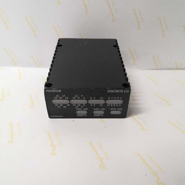
- Communication: 2x 10/100Base-TX (RJ45), Auto-MDIX, Full/HD Duplex
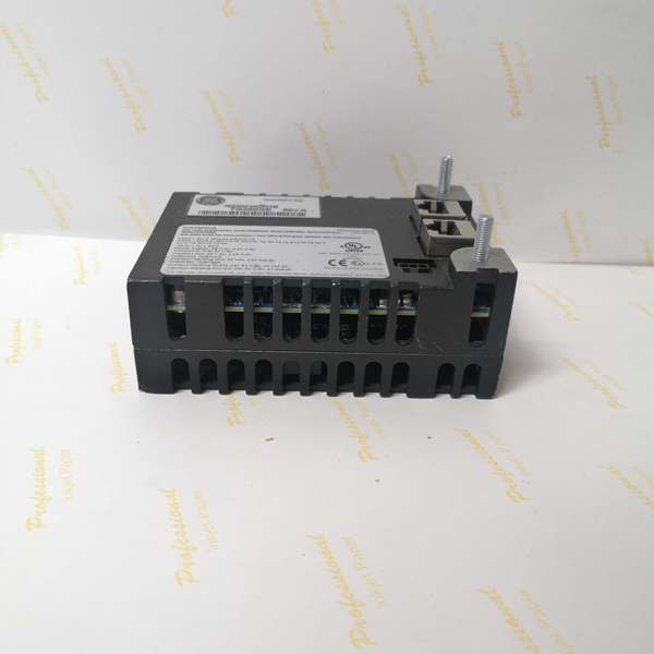
- Field Interface: 1x DC-62 (37-pin D-sub style Male) to TDBS/TDBT
- Power Input: 27.4 – 28.0 V DC (3-pin Micro-Fit connector)
- Isolation: 1500 Vrms (Inputs), 2500 Vrms (Relay Coil to Contacts)
- Diagnostics: Status, Boot, Fault, Active, Net A/B LEDs (Faceplate)
- Mounting: DIN Rail (TS-35) or Direct-to-Board (TDBS/TDBT)
- Environmental: -30°C to +65°C (Operational), Conformal Coated
Customer Value & Operational Benefits
Cabinet Density & Cost Reduction
The “PDIO” concept kills the need for separate input and output packs. By handling 24 DI and 12 DO in one housing, the H1B frees up ~50% of the I/O slots or DIN rail space compared to a PDIA+PDOA pair. In skid-mounted packages or retrofits where panel real estate is tight, this lets you add points without upsizing the enclosure, saving on fabrication and cable tray costs.
Enhanced Noise Immunity (Rev B Upgrade)
Moving from H1A to H1B brings tangible hardware improvements—better EMI/RFI filtering and thermal management. In turbine enclosures where VFD harmonics or exciter switching noise trashes lesser I/O, the H1B’s improved component selection reduces spurious “Input True” events caused by induced voltage on long field runs. This directly cuts down on nuisance alarms and unplanned trips during load swings.
Simplified Spares Logistics
Since one PDIO replaces two different spares (Input Pack + Output Pack), your warehouse only stocks the . Whether a gas compressor station loses a limit switch input or a cooling fan output, the same module works for both. This eliminates the “wrong spare on the truck” scenario at 2 AM and reduces inventory carrying costs.
Field Engineer’s Notes (From the Trenches)
The “Gotcha” on the H1B (inherited from H1A) is the 4ms Hardware Filter. It’s great for cleaning up mechanical contact bounce, but it’s a brick wall for high-speed pulses. If you try to count speed pulses or fast flow meter signals with this pack, it will choke and miss counts because it ignores transitions faster than 4ms. Use a VVIB or PCCA for high-speed; PDIO is for slow-status only (Valve Limits, Pump Run, ESD Contacts).
Another field headache: DC-62 Pin Stress. That 37-pin connector carries all 24 inputs and 12 drive signals. If you mount the pack on a DIN rail separate from the terminal board (using a flying cable), turbine deck vibration will work that connector loose in 6-12 months. Use strain relief clamps on the cable and check the thumb-screws quarterly.
Lastly, power it stiff at 28.0 V DC. The internal drivers drop voltage; if your cabinet supply sags to 24V under load, the terminal board relays (especially 24V coils) may chatter or fail to pull in during a cold start when lube oil viscosity is high.
IS220PDIOH1B
Real-World Applications
- Balance of Plant (BOP) Pump Skids: Mounted on TDBS (Simplex). Inputs 1-10 read “Pump Running” aux contacts and “Low Oil Pressure” switches. Outputs 1-4 drive the starter relays for the lube oil and seal oil pumps. The 4ms filter ignores contact bounce from the mechanical pressure switches.
- Steam Turbine Trip Interlocks (TMR): Three PDIO packs on TDBT boards (R, S, T). They read “Overspeed Trip” dry contacts and “Vacuum Breaker Open” limits. Outputs drive the TRLY coil circuits for Fuel Stop Valve closure. The TMR architecture ensures a loose field wire on R-pack doesn’t trip the unit.
High-Frequency Troubleshooting FAQ
A: Yes. The H1B is a form-fit-function upgrade. The DC-62 pinout, power requirements, and I/O mapping are identical. You can swap it cold (power down the 28V) without changing the ToolboxST project or terminal wiring. The H1B just offers better noise filtering and thermal performance.
Q: ToolboxST shows “PDIO – Attn LED On” or “HW Mismatch” after install. What’s wrong?
A: The pack reads an ID chip on the terminal board. If you landed a TDBS (Simplex) but the controller project is mapped for TDBT (TMR), it will fault. Verify the Terminal Board Type in the I/O Config matches the physical hardware (e.g., IS200TDBSH2Avs IS200TDBTH2A). Also, ensure the 3-pin power plug is fully seated; partial power can cause ID read errors.
Q: Output channel clicks (coil drives) but the field relay doesn’t energize?
A: Check the Fuses on the Terminal Board (TDBS Fuses F1-F6, or TDBT per-channel fusing). The PDIO pack sinks current to drive the coil; if the terminal board fuse is blown or the jumper (JP1-JP6 for voltage select) is set wrong (e.g., 125V setting for 24V coil), you’ll get coil drive voltage but zero current flow. Measure VDC across the terminal board’s coil terminals while commanding ON.
Please note: The listed price is not the actual final price. It is for reference only and is subject to appropriate negotiation based on current market conditions, quantity, and availability.


