
Description
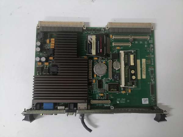
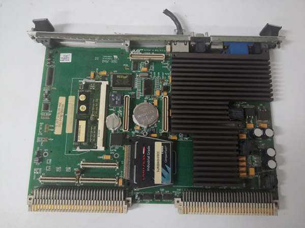
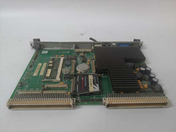
GE IS215UCVEH2A
Hard-Numbers: Technical Specifications
-
Processor: Intel Celeron 300 MHz (Pentium II-based core)
-
L2 Cache: 128 KB
-
DRAM Memory: 32 MB (soldered, non-expandable)
-
Flash Memory: 16 MB or 128 MB CompactFlash (boot storage)
-
Nonvolatile SRAM: 8 KB battery-backed (allocated for controller NVRAM functions)
-
Operating System: QNX real-time operating system
-
Primary Ethernet: 10BaseT/100BaseTX (RJ-45), auto-negotiating
-
Serial Ports: COM1 (RS-232, reserved for diagnostics, 9600 baud default), COM2 (RS-232/RS-485 for Modbus slave, 9600/19200 baud)
-
VMEbus Interface: VME64 compliant, A32/D32 transfer modes, system controller capable
-
I/O Connectivity: VME backplane to VCMI (VME Communication Interface) cards, VAIC (analog input), VSVO (servo), etc.
-
Power Requirements: +5V DC @ 6A typical, 8A max; +12V DC @ 180mA typical, 250mA max; -12V DC @ 180mA typical, 250mA max
-
Operating Temperature: -30°C to +65°C (standard industrial range)
-
Form Factor: 6U VME, single-slot (160mm × 233mm)
-
Dimensions: 8.26 cm high × 4.19 cm (front panel)
-
Weight: 2 lbs (approximate)
-
Reference Manual: GEH-6421M, GEH-6371
The Real-World Problem It Solves
Gas turbine control systems from the 1990s and 2000s needed a rugged, real-time computing platform that could execute complex control algorithms while interfacing with specialized I/O cards over a deterministic backplane. The IS215UCVEH2A drops a complete x86 computer onto a single VME slot, running QNX to handle millisecond-level control loops without the instability of Windows or the complexity of custom RTOS ports.
Where you’ll typically find it:
-
GE Frame 7/9 gas turbine Mark VI control cabinets in power generation plants
-
Mechanical drive applications for compressors and pumps in oil & gas facilities
-
Backup controller roles in triple-modular redundant (TMR) turbine protection systems
This board keeps aging turbine assets operational by providing a maintainable, well-documented control platform that bridges legacy VME I/O with modern Ethernet-based HMI connectivity.

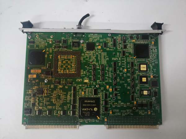
GE IS215UCVEH2A
Hardware Architecture & Under-the-Hood Logic
The IS215UCVEH2A functions as the master controller in a Mark VI VME rack. It does not directly connect to field signals; instead, it orchestrates daughter I/O cards (VAIC, VSVO, VTUR, etc.) via the VME backplane and communicates with the outside world through Ethernet and serial links.
Signal flow and processing logic:
-
CPU Core: The 300 MHz Celeron executes QNX kernel and application control blocks (analog, discrete, Boolean ladder logic). The 128KB L2 cache reduces memory latency for frequently accessed control variables.
-
Memory Architecture: 32 MB DRAM holds the running application and data tables. The 16 MB (or 128 MB) CompactFlash stores the boot image, OS, and compiled blockware. Battery-backed SRAM retains critical parameters (tuning constants, counters) during power loss.
-
VMEbus Master: The board acts as VMEbus master, polling I/O cards via the VCMI (VME Communication Interface) module. It reads analog inputs, writes servo outputs, and handles contact I/O through dedicated VME slave cards.
-
Network Stack: The integrated Ethernet controller runs TCP/IP for Toolbox configuration software, EGD (Ethernet Global Data) protocol for CIMPLICITY HMI, and Modbus TCP for third-party DCS integration.
-
Redundancy Support: In TMR configurations, three UCVE controllers run in parallel, with voting logic handled at the I/O level. Each controller validates its hardware configuration against the Toolbox database on every boot.
-
Watchdog & Diagnostics: Internal watchdog timer monitors task execution. BMAS LED indicates VME master access; fault conditions trigger SYSFAIL or local error codes viewable via COM1 diagnostic port.
Field Service Pitfalls: What Rookies Get Wrong
Ignoring the Battery-Backed SRAM
The 8 KB NVRAM stores calibration data, trip counters, and configuration flags. When the lithium battery dies (typically 5-10 years), the controller loses its mind on next boot—defaulting to factory parameters and potentially tripping the turbine.
-
Field Rule: Check the battery voltage annually during outages. If the “Battery Low” diagnostic appears in Toolbox, replace it immediately. Always back up the NVRAM contents to the CompactFlash before battery replacement. Document every parameter; GE won’t help you reconstruct 20 years of tuning constants.
Mixing UCVE and UCVEM Variants
The base UCVEH2 has one Ethernet port. UCVEM01 through UCVEM10 variants add Profibus, ISBus, DLAN, or secondary Ethernet. If you swap a failed UCVEH2 with a UCVEM spare without updating the Toolbox configuration, the controller halts on boot with a hardware mismatch fault.
-
Quick Fix: Verify the exact part number suffix before installing a spare. If upgrading to UCVEM for additional ports, recompile and download the application from Toolbox to match the new hardware signature. The controller validates P/N on every power-up—no exceptions.
Power Supply Loading on Aged VME Chassis
The UCVE draws up to 8A at +5V. In 20-year-old Mark VI racks, the power supply capacitors are dried out. Adding a second UCVE for redundancy or test purposes can sag the +5V rail below 4.75V, causing intermittent memory errors that look like software bugs.
-
Field Rule: Measure +5V at the P1 connector under full load before declaring a controller faulty. If the rail drops below 4.85V during VME block transfers, replace the chassis power supply or add remote sense wiring. Never trust the front-panel meter; use a DMM at the card edge.


