

Description
Hard-Numbers: Technical Specifications
- Compatible I/O: PPRA Turbine I/O Packs (Requires 3x Packs for TMR configurations)
- Wetting Voltage Output: +24 VDC / -24 VDC / Return Ground (Distributed via JH1 Header)
- Contact Input Channels: 4 Isolated Trip Loops (TRP1L to TRP4L screw terminals)
- Operating Temperature: -30°C to +65°C (Engineered for extreme nacelle and package environments)
- Isolation Rating: 1500 VDC (Field wiring to I/O pack backplane)
- Physical Dimensions: Approx. 10.2 cm W x 33.0 cm H (Standard Mark VIe daughterboard form factor)
- Mounting Style: Direct Plug-in (Daughterboard) / Chassis Mount compatibility
- Connectors: JH1 (Power/Wetting Voltage), Jx (Interface to WREA board), Screw Terminals (TRP)
- Agency Approvals: UL, CE, CSA (Compliant with industrial safety standards)
The Real-World Problem It Solves
You are commissioning a GE LM6000 aeroderivative gas turbine package. The customer requires a foolproof, hardware-level emergency shutdown system that can detect contact closures from mechanical overspeed bolts, low lube oil pressure switches, and manual E-stops. You need a robust terminal board that can provide clean, externally sourced “wetting” voltage to these dry contacts, accurately detect voltage drops across the loops, and seamlessly integrate with the Mark VIe I/O packs—all while resisting the extreme vibration and temperature swings of a jet-engine-based turbine.
Where you’ll typically find it:
- Aero-Derivative Packages: Mounted inside the control cabinet of LM2500, LM6000, or aeroderivative steam turbines.
- High-Speed Mechanical Overspeed Protection Loops: Interfacing directly with mechanical centrifugal overspeed devices.
- Triple Modular Redundant (TMR) Safety Chains: Working in concert with three PPRA I/O packs to execute majority-voting shutdown logic.
It acts as the foundational termination layer for your most critical protection instruments, ensuring that a mechanical failure is translated into an instantaneous, unambiguous electrical shutdown command.
Hardware Architecture & Under-the-Hood Logic
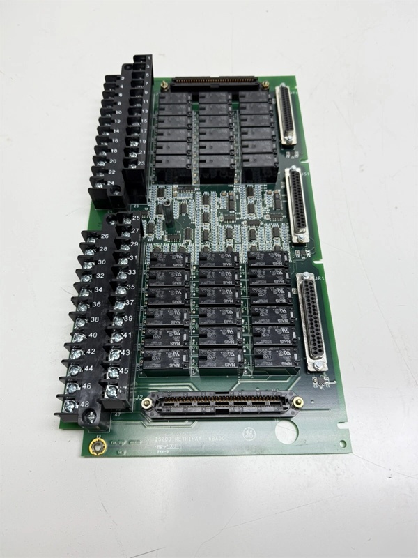
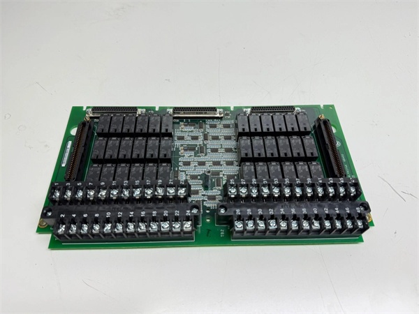
The “S1A” suffix denotes a specific hardware build of the TREA (Terminal Board – Relay/Emergency Trip). This board is designed exclusively to host the WREA option board, creating a highly integrated emergency trip module.
- Precision Wetting Voltage Distribution: The board’s primary job is power management for field contacts. The JH1 connector routes positive (+24V), negative (-24V), and ground (Return) to the screw terminals. This allows the system to use polarized wetting voltages, which helps prevent contact corrosion on critical safety switches in salty or humid offshore environments .
- Commoned Power Bus (PWET): Odd-numbered terminals (PWET) are internally bussed together. This ingenious design means you only need to land your main wetting voltage supply once; it automatically distributes to all connected field devices, drastically reducing panel wiring complexity .
- High-Impedance Voltage Detection: Even-numbered terminals (TRP1L-TRP4L) route the return signal from the field contacts to dedicated voltage detectors. These detectors are optimized to differentiate between a healthy 24V signal and a dropped voltage (contact closure), ensuring zero false positives even in electrically noisy environments .
- Seamless I/O Integration: Once the WREA daughterboard is mated to the IS200WREAS1ACB, the combined assembly plugs directly into the Mark VIe backplane. This routes the conditioned trip signals straight to the PPRA I/O pack processors for immediate action .
Field Service Pitfalls: What Rookies Get Wrong
Reversing Polarities on the JH1 Wetting Voltage Header
A technician is wiring a replacement TREA board. He lands the 24VDC supply on JH1 Pin 3 (Return) and the ground on JH1 Pin 1 (Positive). Because the wetting voltage is reversed, the field contact closures pull the voltage upinstead of dropping it down. The WREA voltage detectors interpret this as a continuous “Healthy” signal. During a real overspeed event, the turbine fails to trip, resulting in a catastrophic overspeed.
- Field Rule: Always use a multimeter to verify polarity at the JH1 header before connecting field wires. Positive wetting voltage MUST land on Pin 1. Double-check the voltage drop across the contact when manually triggered.
Accidentally Breaking the PWET Bus with a Loose Terminal Screw
An installer is tightening the screw for terminal TRP1L (odd-numbered PWET terminal). He over-torques the screw, cracking the internal copper bus bar. Since the PWET terminals are commoned, this single loose connection kills the wetting voltage for allfour trip loops. The HMI suddenly alarms “Multiple Turbine Trips Active,” causing an unnecessary emergency shutdown.
- Quick Fix: Never exceed 5 inch-pounds of torque on TREA terminal screws. After wiring, perform a simple continuity test between all odd-numbered terminals. They should all read near-zero resistance. If one reads open, check for a cracked bus or a loose screw under a neighboring terminal.
Mating the WREA Daughterboard Upside Down
A rookie is installing the WREA option board onto the IS200WREAS1ACB baseboard. He ignores the keying mechanisms and forces the connectors together upside down. This bends the delicate pins in the female headers and shorts the 24VDC wetting voltage directly to the 5VDC backplane logic. The resulting voltage spike fries not just the TREA board, but also the incredibly expensive PPRA I/O pack plugged into the same backplane segment.
- Field Rule: The WREA board has a distinct row of configuration jumpers on its bottom edge. If these jumpers aren’t facing the edge of the chassis (toward the fresh air intake), the board is likely upside down. Never force a daughterboard; if it doesn’t seat with firm, even pressure, stop and re-align it.
Commercial Availability & Pricing Note
Please note: The listed price is for reference only and is not binding. Final pricing and terms are subject to negotiation based on current market conditions and availability.


