
Description
Hard-Numbers: Technical Specifications
- Number of Channels: 4 independent speed input channels
- Input Type: Magnetic pickup, Hall effect, optical encoder, or quadrature encoder
- Input Voltage Range: 0-30 VAC RMS (magnetic pickup), 5-24 VDC (Hall effect/encoder)
- Frequency Range: 0-20 kHz per channel
- Minimum Input Amplitude: 0.5 VAC RMS (magnetic pickup), 3 VDC (digital inputs)
- Zero-Crossing Resolution: 0.1 Hz typical (high-resolution mode)
- Quadrature Decoder: 4x resolution (up to 80 kHz edge count)
- Pulse Per Revolution: Configurable 1-360 PPR (or external encoder resolution)
- Channel Isolation: 1500V RMS between channels and backplane
- Module Power Draw: 2.5A @ 5VDC from backplane
- Backplane Current: 5V: 2.5A max
- Operating Temperature: -20°C to 70°C (-4°F to 158°F)
- Storage Temperature: -40°C to 85°C (-40°F to 185°F)
- LED Indicators: PWR, OK, FAULT, individual channel status LEDs
- Cooling: Forced air (requires Mark VIe backplane cooling fan)
- Module Slot: Mark VIe I/O backplane (any slot in expansion rack)
- Communication: Backplane via TCP/IP (embedded speed processor)
- Firmware Version: Compatible with Mark VIe v5.0 and later
- Alarm Thresholds: Configurable per channel (overspeed, underspeed, loss of signal)

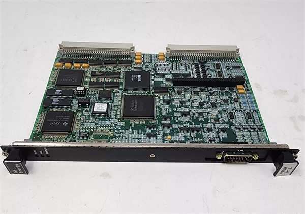
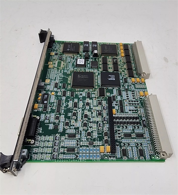
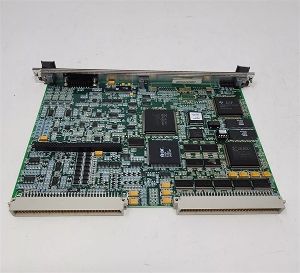
IS200VTURH1B
The Real-World Problem It Solves
Accurate turbine speed is critical for governor control. The IS200VTURH1B provides multi-channel speed input with zero-crossing detection for precise shaft rotation measurement across 4 independent channels. This redundancy ensures reliable speed feedback even if one sensor fails.
Where you’ll typically find it:
- Gas turbine control cabinets with multiple magnetic pickup sensors
- Steam turbine governor systems requiring redundant speed feedback
- Compressor packages with tachometer or encoder-based speed measurement
Bottom line: It gives you redundant, high-precision speed measurement for critical governor applications.
Hardware Architecture & Under-the-Hood Logic
The IS200VTURH1B is a multi-channel speed input module for Mark VIe turbine control racks. Each of the 4 channels has dedicated signal conditioning and frequency measurement circuits. The module supports multiple sensor types: magnetic pickups (AC voltage output from gear teeth), Hall effect sensors (digital pulses), optical encoders (quadrature output), and tachometer generators (analog voltage). Zero-crossing detection provides precise frequency measurement by counting time between zero crossings of the AC input signal. For quadrature encoders, a hardware decoder tracks A and B channel edges to provide 4x resolution and direction detection. An embedded ARM processor manages channel configuration, alarm logic (overspeed, underspeed, loss of signal), and backplane communication. Speed data is transmitted to the main controller via backplane TCP/IP at 1 kHz update rate, ensuring minimal latency for governor control. The module includes selectable low-pass filtering to reject electrical noise while preserving response time.
Internal signal flow:
- Speed sensor input arrives at terminal block
- Signal passes through protection circuits (TVS diodes for transient protection)
- User-configurable signal conditioning (amplification, filtering, offset)
- Zero-crossing detector or quadrature decoder processes signal
- Counter/timer circuit measures time between pulses
- Frequency data is converted to RPM or Hz based on PPR configuration
- Embedded processor formats speed data into Ethernet packets
- Processor communicates with main controller via backplane TCP/IP
- Channel status and diagnostic data are generated for monitoring
- Alarm logic evaluates speed against configurable thresholds
- Overspeed/underspeed/loss of signal alarms are generated if thresholds exceeded
- Front-panel LEDs reflect power status, communication status, and channel faults

IS200VTURH1B
Field Service Pitfalls: What Rookies Get Wrong
Mixing sensor types without reconfiguring causes invalid readingsThe IS200VTURH1B supports multiple sensor types, but channel configuration must match. I’ve seen technicians wire a magnetic pickup to a channel configured for Hall effect, resulting in zero or erratic speed readings.
- Field Rule: Configure each channel for the actual sensor type in Mark VIe software before wiring. Verify jumper settings for AC (magnetic pickup) or DC (Hall effect/encoder) inputs. Test each channel with the actual sensor after installation. Document sensor type per channel in your control system database.
Incorrect PPR configuration creates speed scaling errorsPulses per revolution (PPR) parameter converts frequency to RPM. I’ve seen technicians use default PPR settings, causing speed readings to be off by a factor of 10x or more.
- Field Rule: Verify the actual PPR for each speed sensor. For magnetic pickups, count gear teeth on the shaft. For encoders, read the PPR from the encoder nameplate. Enter the correct PPR value in Mark VIe channel configuration. Verify RPM reading matches a handheld tachometer during commissioning.
Undersized sensor signals cause intermittent loss of speedMagnetic pickup output voltage depends on air gap and shaft speed. I’ve seen technicians install pickups with excessive air gap, causing signal amplitude to drop below 0.5 VAC minimum at low speeds, resulting in speed signal loss.
- Field Rule: Measure magnetic pickup output voltage with a multimeter at minimum operating speed. Voltage should exceed 0.5 VAC RMS across the speed range. If voltage is low, adjust the air gap to manufacturer spec (typically 0.5-1.0 mm). Consider using a preamplifier or switching to Hall effect sensors for low-speed applications.
Ignoring shielding causes noise pickupSpeed sensor cables run long distances through high-noise environments. I’ve seen technicians use unshielded cable, resulting in speed readings with jitter and false overspeed alarms.
- Field Rule: Use shielded twisted pair (STP) cable for all speed sensor wiring. Keep runs under 100 meters (330 feet) to reduce noise. Terminate the shield at the module end only—never at both ends. Separate sensor cables from high-power wiring in conduit or tray. Maintain at least 12 inches of separation from VFD cables.
Forgetting to test overspeed alarms during commissioningOverspeed protection is critical for turbine safety. I’ve seen technicians skip overspeed alarm testing, only to discover the alarm doesn’t trigger at actual overspeed conditions.
- Field Rule: Test overspeed alarms during commissioning and annually thereafter. Simulate overspeed by injecting a frequency signal above the alarm threshold into the module. Verify the alarm triggers and trips the turbine (or activates protection as configured). Test each channel independently. Document overspeed alarm test results in your maintenance log.
Leaving unused channels unterminated causes false alarmsUnused speed input channels pick up noise and trigger false loss of signal alarms. I’ve seen operations teams struggling to clear alarms on channels with no sensors connected.
- Field Rule: Disable unused channels in Mark VIe software configuration. If physical termination is required, connect 1 MΩ resistors to ground. Never leave high-impedance channels unterminated—this creates antenna-like noise pickup. Document disabled channels in your installation records.
Commercial Availability & Pricing Note
Please note: The listed price is for reference only and is not binding. Final pricing and terms are subject to negotiation based to current market conditions and availability.


