
Description
Hard-Numbers: Technical Specificiations
- Sync Link Voltage: 24 VDC (Nominal, range 20-28VDC)
- Sync Link Current Draw: < 300 mA per controller link
- Controller Support: 2 controllers maximum (M1 primary, M2 backup)
- Isolation Rating: 1500V AC (Sync bus to backplane logic)
- Operating Temperature: -40°C to +85°C
- Redundant Architecture: 1oo2 (One-out-of-Two) Voting Logic
- Communication Interface: Proprietary Sync Link (Hardwired 24VDC)
- Trip Relay Outputs: 2 Form-C Relays (250VAC/30VDC rating)
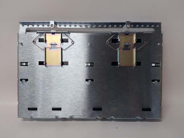
- Mounting Location: Exciter Power Backplane Rack (EPBP)
- Diagnostic LEDs: M1 Active, M2 Active, Sync Healthy, Trip Relay Energized
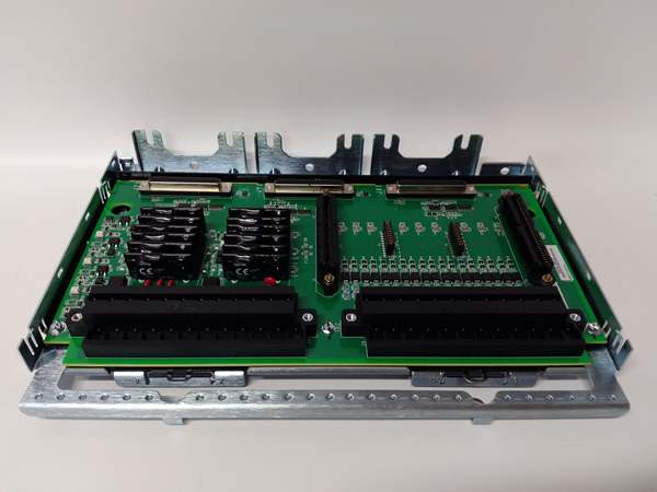
IS200TREAS1A
The Real-World Problem It Solves
You’re troubleshooting a 9FA gas turbine where the plant management refused to pay for full triple-redundant (TMR) architecture, opting instead for a cost-effective dual-controller setup. The old simplex interface card has a nasty habit of dropping gate pulses for 50 milliseconds during M1-to-M2 failovers, causing the AVR to hunt and occasionally trip the unit. You need a board that can execute a deterministic, sub-millisecond handover between two controllers using a simplified but robust voting logic. This S1A variant eliminates that headache. It acts as the streamlined traffic cop for your dual-controller excitation system, ensuring the backup takes over the instant the primary stumbles.
Where you’ll typically find it:
- Cost-Optimized EX2100/EX2100e Installations: Dual-controller setups where full TMR was deemed unnecessary or budget-prohibitive.
- Biomass & Small Cogeneration Plants: Smaller synchronous generators (50-200MW) running dual-redundant excitation without the complexity of triple modular redundancy.
- Retrofit Projects: Converting legacy single-controller static exciters to dual-redundant architecture with minimal cabinet footprint increase.
It turns a potentially catastrophic 50ms control gap into a deterministic, sub-millisecond controller handover.
Hardware Architecture & Under-the-Hood Logic
This board isn’t a full TMR voting engine; it’s a streamlined dual-controller arbitrator built for simplicity and reliability. It lives on the EPBP backplane, acting as the decisive judge between your primary (M1) and backup (M2) excitation controllers. The “S1A” suffix indicates simplified architecture with optimized trace routing and reduced component count for enhanced MTBF in dual-redundant applications.
- Dual Sync Link Acquisition: Two hardwired 24VDC sync links arrive from controllers M1 and M2. Dedicated comparators on the TREA constantly monitor voltage integrity and pulse timing to detect controller degradation before catastrophic failure.
- 1oo2 Voting Logic Execution: When both M1 and M2 assert “Master Ready” signals, the onboard logic implements a 1oo2 (One-out-of-Two) vote. If M1 fails or drops its heartbeat, the TREA doesn’t wait for software intervention—it instantly gates the sync bus to M2 within one millisecond.
- Deterministic Failover Gating: Upon detecting primary controller failure, the TREA activates high-speed analog switches. These sever the M1 gate pulse path and connect M2’s pulses to the EGPA boards, ensuring continuous excitation without dropping below the thyristor holding current.
- Simplified Trip Relay Logic: Two Form-C relays provide a fail-safe protection path. If both controllers fail or a catastrophic fault is detected, both relays de-energize simultaneously, opening the generator breaker and discharging the field winding.
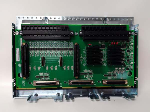
IS200TREAS1A
Field Service Pitfalls: What Rookies Get Wrong
Attempting to Run Three Controllers on an S1A Board
A rookie upgrades a plant from dual to triple redundancy and keeps the S1A board installed, trying to land all three sync links (M1, M2, C) onto its terminals. The S1A’s 1oo2 voting logic can’t handle a third controller. It enters an infinite arbitration loop, constantly switching between masters and causing the AVR to oscillate wildly until it trips the turbine.
- Field Rule: The S1A variant supports exactly two controllers (M1 and M2). If you need triple redundancy (M1, M2, C), you must upgrade to the H2 variant (IS200TREAH2A). Never try to force three sync links onto a dual-controller board—you’ll create a control oscillation nightmare.
Using Undersized Wire for 24VDC Sync Links
A junior engineer lands the 24VDC sync links using leftover #20 AWG thermostat wire from the instrumentation spool. During a peak load rejection event, the TREA draws 250mA through each sync link. The undersized wire drops 1.5 volts, reducing the sync voltage to 22.5VDC. The TREA declares “Sync Link Undervoltage” and triggers a spurious controller handover mid-ramp.
- Quick Fix: Always use minimum #18 AWG (1mm²) stranded copper wire for 24VDC sync links. Crimp on compression lugs rated for 5 amps continuous. Measure the actual voltage drop under load—it must stay above 22VDC at the TREA terminals.
Ignoring the Sync Link Polarity When Landing Wires
A mechanic is connecting the M2 sync link to the TREA. He’s rushing because it’s 105°F in the turbine hall. He reverses the positive and negative leads. He energizes the system, and the TREA detects reverse polarity on the M2 link. It immediately flags “Sync Link Conflict,” locks out the backup controller, and forces the system into simplex mode with zero redundancy.
- Field Rule: Before tightening a single screw, use a multimeter to verify polarity on every sync link wire end. Match the color codes exactly to the legacy drawings. A reversed sync link polarity is a silent killer of redundant architectures—you’ll think you have backup protection when you actually don’t.
Commercial Availability & Pricing Note
Please note: The listed price is for reference only and is not binding. Final pricing and terms are subject to negotiation based on current market conditions and availability.


