
Description
Hard-Numbers: Technical Specificiations
- Supply Voltage: 12 to 30 VDC (Self-powered from EX2100e control, requires dual 28V feeds for redundancy)
- Dry Contact Input Channels: 4 independent channels (configurable for Gen Breaker Aux, 52G, etc.)
- Contact Wetting Current: 5-10 mA (burns through contact oxidation)
- Signal Isolation: 1500V AC (Input terminals to internal logic)
- Communication Interface: 2 x HSSL Fiber Optic Ports (RJ-45 interfaces to EX2100e controllers)
- Operating Temperature: -30°C to +65°C
- Signal Debounce: Configurable 0 to 255 ms (via DIP switches or software)
- Mounting Location: Exciter Power Backplane Rack (EPBP)
- Connectors: Phoenix Terminal Blocks (Input), IDC Headers (HSSL)
The Real-World Problem It Solves
You’re troubleshooting a 9FA gas turbine that keeps tripping on “Gen Breaker Status Mismatch” during high winds. The raw dry contact signal from the 4160V generator breaker is picking up massive EMI from nearby lightning strikes and HV switchgear operations. This noise tricks the EX2100e controller into thinking the breaker opened and closed ten times in a second. You need a hardened interface that can scrub the electrical hash, debounce the signal, and send a clean, fiber-optic isolated status to the controller. This GDDM board eliminates that nightmare. It acts as the bulletproof gatekeeper between the brutal high-voltage switchyard and your sensitive excitation logic.
Where you’ll typically find it:
- EX2100e Exciter Cabinets: Mounted on the EPBP backplane, serving as the primary interface for generator breaker auxiliary contacts and interlock signals.
- Large Combined-Cycle & Nuclear Plants: Providing high-integrity breaker status feedback in environments prone to severe electrical transients.
- Retrofit Projects: Replacing legacy electromechanical relay panels to achieve deterministic breaker status monitoring via fiber optics.
It turns a noisy, unreliable dry contact signal from the switchyard into a pristine, electromagnetically isolated status bit for your excitation controller.
Hardware Architecture & Under-the-Hood Logic
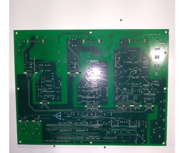
This board doesn’t run a microprocessor; it’s a hardened signal conditioner and optical isolator. It lives on the EPBP backplane, acting as the ultimate translator between the grungy 125VDC plant environment and the pristine 3.3V logic of the EX2100e. The “ABA” suffix indicates project-specific firmware and enhanced trace routing for high-noise environments.
- Dry Contact Conditioning & Wetting: Raw 125VDC signals from the generator breaker aux contacts land on the Phoenix terminal blocks. They immediately pass through precision current-limiting resistors that provide 5-10mA of wetting current, burning through any oxidation on the mechanical contacts.
- Optical Isolation & Level Shifting: The conditioned contact signal hits an optocoupler with 1500V isolation. This completely severs the electrical connection between the plant’s dirty ground and the board’s internal logic. The signal is level-shifted to the 3.3V/5V logic levels required by the HSSL link.
- Debounce Logic & State Latching: Integrated RC filters and timing circuits apply the configured debounce delay (e.g., 50ms). This ensures a bouncing mechanical relay doesn’t register as multiple events. The final clean state is latched and prepared for transmission.
- HSSL Fiber Optic Transmission: The clean status bit is serialized and driven onto the two HSSL fiber optic ports (RX/TX). It travels via ruggedized multimode fiber to the EX2100e controller, completely immune to any further electrical noise along the cable run.
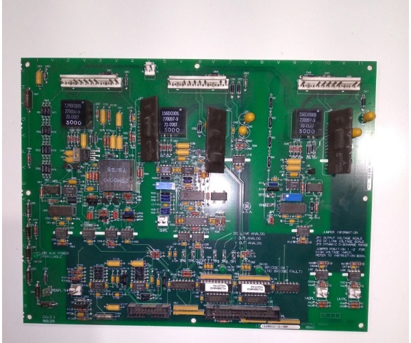
GE IS200GDDDG1ABA
Field Service Pitfalls: What Rookies Get Wrong
Reverse-Polarizing the 28VDC Power Feeds
A rookie is landing the dual 28VDC feeds from the EX2100e control sections (M1 and M2) onto the GDDM’s power terminals. He gets the polarity backwards on one feed. He powers up the system, and the reverse voltage immediately fries the input protection diodes. The GDDM dies, losing all breaker status, and the turbine refuses to synchronize.
- Field Rule: Before tightening the first screw, verify polarity with a multimeter on the bare wires. Look for the “+” and “-” markings on the terminal block housing. A reversed 28VDC feed is an instant board killer. Double-check your work before applying power.
Setting Debounce Time Too Low for Old Mechanical Relays
A junior engineer installs a new GDDM connected to a 40-year-old generator breaker. He leaves the debounce time at the default 0ms. Every time the breaker operates, the mechanical contacts bounce for 80ms. The GDDM reports this as “Rapid Open/Close Cycles,” triggering a “Breaker Chatter” protection trip.
- Quick Fix: Analyze the mechanical characteristics of your specific breaker aux contacts. Set the debounce time in the ToolboxST configuration to at least 100ms for older, bouncier relays. Watch the signal trend to ensure the “Closed” state stays solid during operation.
Kinking or Crushing the HSSL Fiber Optic Patch Cables
A mechanic is routing the HSSL fiber patch cables from the GDDM to the EX2100e controller. He pulls the cable tight around a sharp 90-degree bend in the cable tray to make it look neat. The bend radius is too tight, crushing the internal glass fibers. The optical link goes dark, and the controller declares “Gen Breaker Status Loss,” tripping the unit.
- Field Rule: Respect the minimum bend radius for multimode fiber (usually 10x the cable diameter). Never staple or zip-tie fiber cables tightly. Use gentle curves and proper cable management trays. A broken fiber link is often just a crushed cable, easily fixed with a new patch cord.
Commercial Availability & Pricing Note
Please note: The listed price is for reference only and is not binding. Final pricing and terms are subject to negotiation based on current market conditions and availability.


