
Description
Hard-Numbers: Technical Specifications
- Input Voltage / Power: 28 V DC (per control section; board-local conversion from 28 V DC)
- Input Voltage Range (Pack): 5 V DC / 24 V DC (as provided to the pack)
- Output Voltage Range: 5 V DC – 250 V AC
- Number of Input Channels: 24
- Input Isolation (in pack): 1500 V
- Potential Transformer (PT) Inputs: 4 × 120 V AC (3-phase + neutral)
- Current Transformer (CT) Inputs: 2 standard CTs (configurable 5 A or 1 A)
- Relay Outputs (Trip): 2 (trip relay outputs to drive customer lockout device)
- Operating Temperature: 0°C to +55°C
- Mounting Type: DIN Rail
- Size: 15.875 cm (H) × 10.795 cm (W)
- HSLA Comms Interface: RJ-45 (CAT5e Ethernet)
- Manual Reference: GEI-100772
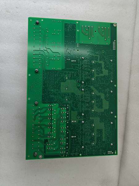
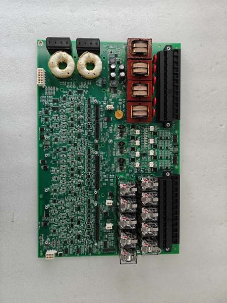
GE IS200ESYSH1AAA
The Real-World Problem It Solves
You are troubleshooting a combined-cycle unit where the plant DCS keeps flagging “Generator VT Loss” or “Customer Trip Ack Missing” every time a breaker operation spikes the 48 V DC panel. The root cause is often a mismatch between the site’s 120 V PT/CT wiring practice and the ESYS’s fanned distribution, or a daughterboard seating issue that causes intermittent HSSL dropouts. You need a board that cleanly terminates PT/CT and customer I/O, isolates the field side, and talks deterministically to the EX2100e control via HSSL daughterboards—so you don’t lose excitation supervision when it matters most.
Where you’ll typically find it:
- EX2100e exciter regulator cabinets interfacing to generator PT/CT and customer lockout/trip relays.
- Site/utility I/O islands where customer analog I/O and general-purpose relay outputs are required alongside trip relays.
- Redundant EX2100e applications using M1/M2/C logic with HSSL daughterboard(s) per control section.
It converts a messy, noise-prone site I/O bundle into a deterministic, isolated interface that the EX2100e control can trust.
Hardware Architecture & Under-the-Hood Logic
This is not a general-purpose PLC I/O slice; it is a purpose-built EX2100e interface that combines measurement, isolation, and deterministic communication in one package. Each control section (e.g., M1/M2) gets its own 28 V DC feed and its own HSLA daughterboard, so a single supply failure does not take down the whole I/O set. The 1500 V isolation in-pack helps keep field-side transients away from the control-side logic during breaker operations and lightning events.
- Power Entry & Local Regulation: The board receives 28 V DC per control section; it uses this directly and generates other local supplies on-board. HSLA daughterboards also receive 28 V DC and produce 3.3 V DC for board operation.
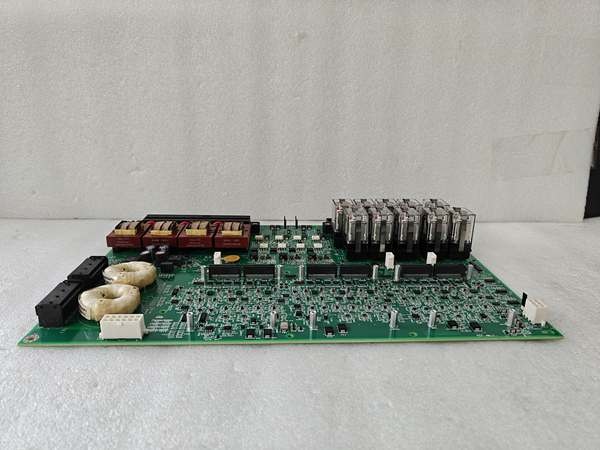
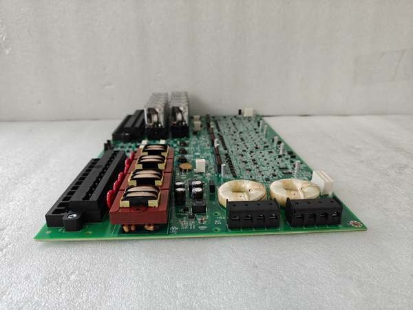
- Measurement Front-End (PT/CT & Analog): Isolation transformers handle generator voltage measurement; the board accepts two 3-phase PT inputs and CT inputs, plus two customer analog inputs (scaled/converted per section).
- Contact I/O & Relay Drive: Seven general-purpose contact inputs and four GP relay outputs (2oo3 voting at coil driver) provide plant interfacing; two trip relay outputs drive the customer lockout device.
- HSSL Link to EX2100e Control: HSLA daughterboards provide RJ-45 Ethernet-style HSSL with FPGA-based handling; board IDs and power-good/undervoltage detection support redundancy and diagnostics.
GE IS200ESYSH1AAA
Field Service Pitfalls: What Rookies Get Wrong
Treating the 28 V DC as “any 24 V supply”
A junior tech lands a 24 V DC plant supply onto the 28 V DC terminals because “it’s close enough.” The ESYS/HSLAs see undervoltage, the HSSL link flaps, and the EX2100e control declares I/O unhealthy, forcing a nuisance trip during synchronization.
- Field Rule: Verify the 28 V DC nominal supply is correctly sourced and fused; confirm polarity and tightness; then power up and validate HSSL link LEDs before closing any I/O loops.
Fanning PT/CT to wrong control sections
A rookie fans both PT inputs to M1 and leaves M2 unterminated, but the EX2100e application expects redundant measurement fanned to both M1 and M2. After a planned M1 power-down, the system loses generator voltage feedback and goes into protection.
- Field Rule: Follow the single-line/application drawing for fanning rules: PT/CT often fan to each control section; leave nothing “half-terminated” unless the design explicitly says so.
Seating HSLA daughterboards poorly (then blaming HSSL)
A mechanic swaps ESYS but forgets to torque the four standoffs per HSLA before carrier assembly. Vibration during start-up loosens the HSLA press-fit, links drop, and you spend hours chasing “communication loss” that looks like a network problem.
- Field Rule: Install HSLA standoffs tight before mounting ESYS to the carrier; confirm the carrier fully supports the board perimeter; use wrist straps; verify RJ-45 link LEDs after reassembly.
Skipping eyelet grounding and creating ground-loops/noise
A technician leaves the ESYS eyelets ungrounded “because it worked last time.” A lightning event or 4160 V bus switching injects common-mode noise; the 1500 V isolation fights it, but the ungrounded chassis becomes a floating antenna and trips protection intermittently.
- Field Rule: Install the two eyelet grounding screws through the carrier into the grounded bracket; keep cable shields terminated to the grounded carrier/panel per site standards to minimize noise coupling.
Commercial Availability & Pricing Note
Please note: The listed price is for reference only and is not binding. Final pricing and terms are subject to negotiation based on current market conditions and availability.


