
Description
Hard-Numbers: Technical Specificiations
- Input Voltage: 125 VDC (sourced from station battery bus)
- Output Voltages: 24 VDC and 5 VDC (regulated, ±1%)
- Total Output Current: Up to 20 Amps (combined continuous)
- Architecture Mode: Simplex (single-channel, non-redundant)
- Operating Temperature: -20°C to +60°C
- Isolation Rating: 1500V input-to-output
- Mounting Location: Exciter Power Backplane Rack (ERBP)
- Onboard Protection: Input & Output Fuses/Circuit Breakers
- Diagnostic LEDs: Input Power, 24VDC Power, 5VDC Power, Fault
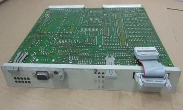
GE IS200ERSCG2A
The Real-World Problem It Solves
You are troubleshooting a small biomass cogeneration unit where a full redundant power system is pure overkill and a massive waste of capital. The old linear power supply keeps sagging under the load of a single DSPX processor, causing the excitation control to brown out and trip the turbine on “AVR Processor Fault.” You need a power module that can take the 125VDC station battery and spit out rock-solid 24VDC and 5VDC without flinching. This ERSM board eliminates that headache. It’s built for simplex architectures, delivering deterministic power to all your control electronics without bloating the budget or the cabinet footprint.
Where you’ll typically find it:
- Small Biomass & Cogeneration Plants: Powering EX2100 racks in single-architecture excitation setups.
- Industrial Steam Turbine Generators: Serving as the primary power backbone for small- to medium-sized synchronous generators.
- Legacy Plant Retrofits: Replacing bulky, heat-generating transformer-based power supplies in existing control cabinets.
It turns a brittle, voltage-sagging single-point power supply into a reliable, deterministic energy source for your excitation control.
Hardware Architecture & Under-the-Hood Logic
This isn’t a complex redundant power manager; it’s a straightforward, high-efficiency switch-mode power supply built to survive the dirty electrical environment of a power plant control room. It lives on the ERBP backplane, acting as the single-source power workhorse for your simplex excitation system. The “G2A” suffix indicates optimized component selection for enhanced thermal performance and MTBF in non-redundant setups.
- Input Conditioning & Surge Suppression: The 125VDC input first hits an EMI filter and surge suppressor. This scrubs the electrical hash from the station battery bus before it can fry downstream processors.
- High-Frequency Switching Conversion: An internal PWM controller drives a power MOSFET at high frequency. This chops the 125VDC into a high-frequency AC waveform, which is then stepped down via a compact transformer and rectified into clean 24VDC and 5VDC rails.
- Simplex Power Output & Distribution: Unlike the redundant G1A models, this board does not communicate with a second ERSM for load sharing. It acts as the sole power source for the entire rack, delivering up to 20 amps of continuous current to the DSPX, EDEX, EGDM, and all I/O terminal boards.
- Real-Time Health Monitoring: The onboard microcontroller watches input voltage, output current, and internal temperature. If the output sags or a short occurs, it trips the onboard protection and lights up the Fault LED.
Field Service Pitfalls: What Rookies Get Wrong
Installing a G2 Simplex Board in a Redundant Architecture
A rookie pulls a fried IS200ERSMG1A from a triple-redundant 9FA gas turbine and swaps it with a warehouse-stock IS200ERSMG2A. The turbine powers up, but the EMIO throws a “Power Redundancy Mismatch” alarm and refuses to arm the excitation system. The G2 hardware is hardcoded for simplex logic and cannot participate in load-sharing configurations.
- Field Rule: Always match the hardware revision suffix to your power architecture. If your system uses redundant (load-sharing) power supplies, you mustuse the G1A variant. The G2 variant is exclusively for simplex architectures. Never try to force a simplex board into a redundant system.
Using Undersized Wire for the 125VDC Input Lugs
To snake through a cramped cable tray, a junior engineer reuses some leftover #16 AWG wire for the 125VDC input from the station battery. During a peak load ramp, the ERSM draws 20 amps of continuous current. The undersized wire heats up to 110°C, melts the insulation, and creates a short circuit that blows the plant’s entire 125VDC distribution breaker.
- Quick Fix: Use minimum #12 AWG (4mm²) stranded copper wire for the 125VDC input. Crimp on heavy-duty compression lugs and torque them down to 15 lb-in. Apply a thin layer of anti-oxidizing paste to the lugs to prevent corrosion-induced resistance creep.
Attempting to Parallel Two G2 Boards for “Fake Redundancy”
A mechanic wants to add redundancy to a simplex system, so he installs two G2 ERSM boards in parallel. He doesn’t realize that the G2 variant lacks the load-sharing communication logic. The two boards fight each other for control of the 24VDC bus, leading to wild voltage oscillations and the eventual failure of both power supplies.
- Field Rule: Never attempt to parallel two G2 simplex ERSM boards. If you need redundancy, you must purchase and install two G1A redundant variants. The G2 boards are not designed to communicate or share loads and will destroy each other if forced to do so.
Commercial Availability & Pricing Note
Please note: The listed price is for reference only and is not binding. Final pricing and terms are subject to negotiation based on current market conditions and availability.


