
Description
Hard-Numbers: Technical Specificiations
- Supply Voltage: 24 VDC (sourced from excitation voltage)
- Analog Output Signal: 0–20mA (ground-fault signal transmission)
- Maximum Lead Resistance: 15 Ω
- Operating Temperature: -40°C to +70°C / +85°C
- Compliance Standards: GEI-100462, SWC C37.990 (EMI/RFI immunity)
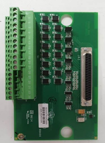
- Connectors: J1 (9-pin vertical plug), TB1 & TB2 (4-position terminal strips)
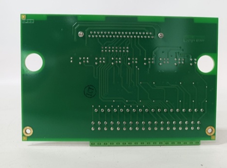
- Mounting Options: DIN-rail or Wall/Panel mount (using E1-E4 grounding holes)
- Key Output Signals: Ground Alarm, Ground Detector Malfunction, Diode Fault Monitor
GE IS200ERGTH1AAA
The Real-World Problem It Solves
You’re troubleshooting a coastal 9FA gas turbine that keeps tripping on vague “Field Ground Fault” alarms. The internal EGDM module can’t accurately quantify the leakage resistance through the salt-contaminated rotor winding. You need a direct, hardwired pathway to hook up a high-precision, third-party ground detector (like Bender or Megger) into the EX2100’s EROC logic. This ERGT board eliminates that guessing game. It acts as the physical and electrical bridge between the EROC options card and your external detector, delivering crystal-clear ground fault telemetry and diode health checks without a hint of electrical noise.
Where you’ll typically find it:
- EX2100 Exciter Cabinets: Externally mounted (DIN rail or wall) to interface third-party detectors with the ERBP/ERRB backplanes.
- Coastal & Offshore Platforms: Providing ultra-high-sensitivity ground fault detection in high-salinity, high-EMI environments.
- Retrofit Projects: Integrating legacy analog ground detectors into modern digital excitation control architectures.
It turns a vague, unquantified ground fault alarm into a precise, actionable resistance reading for your operations team.
Hardware Architecture & Under-the-Hood Logic
This board isn’t a processor; it’s a specialized passive signal translator and interface adapter designed for maximum durability in harsh plant environments. It hangs off the main excitation rack, acting as the physical liaison between the digital EROC card and the analog world of third-party safety equipment. The “AAA” suffix indicates specific RoHS 6/6 lead-free soldering and enhanced manufacturing traceability.
- EROC Signal Acquisition: The board connects directly to the Exciter Regulator Options Card (EROC) via a vertical 9-pin plug connector (J1). It pulls the raw detection logic and status bits from the EROC’s backplane intelligence.
- Signal Conversion & Terminal Breakout: It translates the internal signals into physical screw terminal connections. The dual 4-position terminal strips (TB1 and TB2) provide the ruggedized landing points for your third-party detector’s output relays and analog transmitters.
- Triple-Fault Logic Distribution: Based on the EROC input, the ERGT routes three critical safety signals to your external devices: a standard Ground Alarm, a Ground Detector Malfunction alert (telling you if the detector itself died), and a Diode Fault Monitor (watching the health of the rectifier diodes).
- Localized Chassis Grounding: Unlike internal rack cards, this board uses four specific mounting holes (E1-E4). These are explicitly designed to be tied into the cabinet’s chassis ground, ensuring the third-party detector’s zero-reference is rock solid amidst the plant’s electrical hash.
GE IS200ERGTH1AAA
Field Service Pitfalls: What Rookies Get Wrong
Connecting the Third-Party Detector With a Floating Shielded Cable
A rookie lands the shielded twisted-pair cable from the Bender ground detector onto the TB1/TB2 terminals. He grounds the shield at the detector end but leaves it floating at the ERGT end. The massive EMI from the nearby 4160V switchgear induces ghost voltages on the shield, tricking the ERGT into thinking there is a permanent ground fault.
- Field Rule: Always ground the shield drain wire at the ERGT terminal strip end using the dedicated chassis ground points (E1-E4). Use high-quality, braided-shield twisted pair cable. A floating shield is a guaranteed antenna for spurious ground fault trips.
Zip-Tying the Board to a Cable Tray Instead of Proper Mounting
A junior engineer is retrofitting a 9FA plant. To save space, he zip-ties the ERGT board to a cable tray instead of using the DIN rail or wall mounts. He completely ignores the E1-E4 mounting holes. During a lightning storm, a voltage surge finds no low-impedance path to ground through the ERGT, frying the J1 connector and the EROC card behind it.
- Quick Fix: You must physically mount this board using the designated holes (E1-E4). Use short, heavy-gauge copper braid straps to connect those mounting points directly to the painted-and-scraped clean metal of the exciter cabinet. No ground strap, no surge protection.
Forcing the J1 9-Pin EROC Connector In Upside Down
A mechanic rushes to swap a suspected bad ERGT board. He forces the 9-pin plug from the EROC into the J1 socket upside down, bending two of the delicate male pins on the EROC card. The turbine refuses to sync because the Diode Fault Monitor signal is permanently shorted to ground.
- Field Rule: The J1 connector has a distinct keying notch. Never force the connector. If it doesn’t slide in smoothly, pull it back out and rotate it 180 degrees. Bent pins on an EROC card are a nightmare to repair and usually result in writing off a $15,000 component.
Commercial Availability & Pricing Note
Please note: The listed price is for reference only and is not binding. Final pricing and terms are subject to negotiation based on current market conditions and availability.


