
Description
Hard-Numbers: Technical Specificiations
- Operating Voltage: 24 VDC
- Operating Temperature: -40°C to +85°C
- Board Dimensions: 2 cm (H) x 18.6 cm (W) x 26.1 cm (D)
- Weight: ~0.36 kg (0.79 lbs)
- Humidity Range: 5%–95% non-condensing
- Operation Modes: Simplex & Redundant
- Relay Control: K3 (Charging, Simplex) / K41 (Discharge, Redundant)
- Mounting Locations: ERBP backplane (Simplex) & ERRB backplane (Redundant secondary)
- Feedback Signals: Bridge output, DC link voltage, Shunt current, IGBT gate drive, Bridge temp
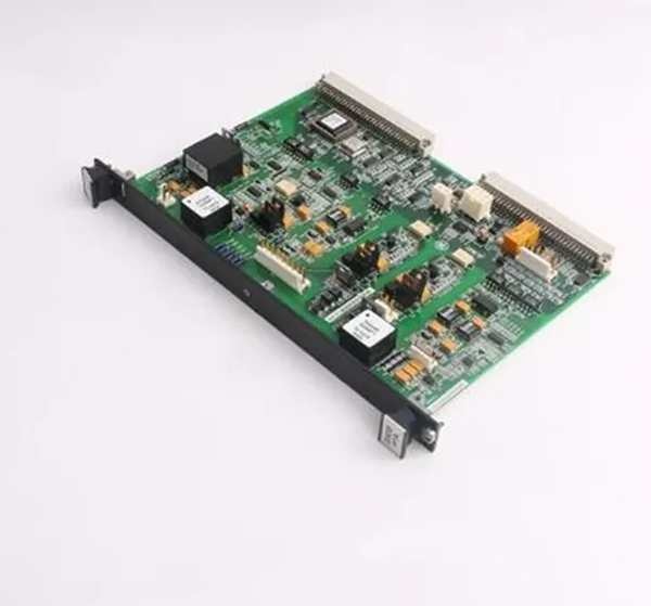
GE IS200ERDDH1A
The Real-World Problem It Solves
You’re troubleshooting a 9FA gas turbine that just experienced a massive “DC Link Overvoltage” event during a load rejection. The old discharge path was relying on slow-acting contactors that couldn’t dump the field energy fast enough, cooking the thyristor bridge and threatening a $2M rotor rewind. You need a board that can monitor the bridge temperature and gate drive status in real-time, then trigger an aggressive dynamic discharge when things go south. This ERDD board eliminates that nightmare. It provides a deterministic, high-speed path to bleed off dangerous DC link voltage before the bridge melts down.
Where you’ll typically find it:
- EX2100 Exciter Control Cabinets: Installed on the ERBP backplane (simplex) or split between ERBP and ERRB (redundant) for dynamic discharge control.
- Large Combined-Cycle Power Plants: Protecting multi-megawatt thyristor bridges during emergency shutdowns and load rejections.
- Retrofit Projects: Upgrading slow mechanical discharge contactors to fast-acting electronic discharge paths in legacy excitation systems.
It turns a sluggish, damage-prone overvoltage protection scheme into a deterministic, millisecond-response discharge loop.
Hardware Architecture & Under-the-Hood Logic
This board isn’t a microprocessor-based controller; it’s a dedicated analog/digital hybrid circuit designed to watch the excitation system’s pulse and react instantly. It lives on the ERBP or ERRB backplane, acting as the discharge command center for your thyristor bridge. The “H1A” suffix indicates optimized trace routing and enhanced component selection for harsh environments.
- Bridge Feedback Acquisition: The ERDD continuously monitors four critical signals via backplane connections: output field voltage/current, DC link voltage, shunt current, IGBT gate drive status, and bridge temperature. It builds a real-time health picture of the power bridge.
- Overvoltage Threshold Detection: Analog comparators continuously compare the DC link voltage against a preset threshold. When the voltage exceeds the safe operating envelope, the board triggers its discharge logic without waiting for the main DSPX processor to wake up.
- Mode-Dependent Relay Actuation: In simplex mode, the ERDD fires the K3 charging relay to manage the field winding’s energy storage. In redundant mode, it commands the K41 discharge relay to create a low-impedance path that rapidly dissipates the DC link energy into the discharge resistor bank.
- Gate Drive Status Reporting: The board monitors the IGBT gate drive signals from the EGPA/EHPA boards. If it detects a stuck-on gate or a failed drive circuit, it immediately initiates a protective discharge sequence and reports the fault to the DSPX via the backplane.
Field Service Pitfalls: What Rookies Get Wrong
Installing the Board in the Wrong Backplane for the Operating Mode
A rookie is setting up a redundant excitation system and installs both ERDD boards on the ERBP backplane. During commissioning, the redundant discharge path never activates because the second ERDD (which should control K41 on the ERRB) can’t reach its target relay. The turbine passes commissioning but fails catastrophically during the first real load rejection.
- Field Rule: In redundant mode, you need two ERDD boards. Install one on the ERBP backplane and the second on the ERRB backplane. The ERRB-mounted board specifically controls the K41 discharge relay. Mixing up the mounting locations breaks the redundant protection scheme.
Ignoring the DC Link Voltage Calibration After Replacement
A mechanic replaces a failed ERDD and skips the calibration routine. The board’s internal voltage divider resistors have a slight tolerance variance from the factory spec. During a minor grid disturbance, the ERDD thinks the DC link hit 800V when it only reached 520V. It triggers a premature discharge, tripping the turbine and costing the plant $100K in lost generation.
- Quick Fix: After installing a new ERDD, perform the DC link voltage calibration using ToolboxST or the local HMI. Verify the board’s voltage reading matches a calibrated HV probe within 2%. A miscalibrated discharge board is worse than no discharge board at all.
Letting the Gate Drive Sense Leads Vibrate Loose
A technician reroutes cables in the exciter cabinet and doesn’t secure the small-gauge gate drive sense leads from the EGPA boards to the ERDD. The constant low-frequency vibration from the turbine causes one lead to work loose over three months. The ERDD loses visibility into the IGBT gate status and can’t detect a failed drive. When a real overvoltage event occurs, the discharge sequence never triggers.
- Field Rule: Strain-relieve all gate drive sense leads with nylon tie-wraps or adhesive-backed cable clips. Apply a dab of hot glue at the termination point. Test continuity with a multimeter after any cable tray work near the ERDD. Blind spots in discharge protection are a guaranteed rotor-killer.
Commercial Availability & Pricing Note
Please note: The listed price is for reference only and is not binding. Final pricing and terms are subject to negotiation based on current market conditions and availability.


