
Description
Product Introduction
The is a Group 1 Exciter Power Supply Module (EPSMG1) designed specifically for the EX2100 Excitation Control System within the Mark VI turbine architecture. Unlike the G2 variants used for regulator control, this G1 unit is dedicated to powering the excitation control circuits.
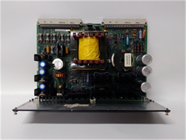
It accepts a nominal 125 Vdc input (typically from the EPDM – Power Distribution Module) and internally converts it via a buck-regulator and push-pull inverter to provide isolated DC rails: +5 Vdc (logic), ±15 Vdc (analog), +24 Vdc (fan/relay power), and an isolated +70 Vdc (for contact wetting on terminal boards). The “AFC” suffix indicates it is an ‘A’ revision board with specific conformal coating (C-grade) and component variations for enhanced reliability in harsh turbine environments. It mounts vertically into the EPBP (Exciter Power Backplane) located beneath the main control backplane.
IS200EPSMG1AFC
Key Technical Specifications
- System Role: EPSMG1 (Group 1 – Excitation Control Power)
- Input Voltage: 125 Vdc (Nominal, from EPDM)
- Key Outputs:
- +5 Vdc (Logic/Processor Power)
- +15 Vdc / -15 Vdc (Analog Circuitry)
- +24 Vdc (Fans, Crowbar, Detectors, Relays)
- +70 Vdc (Isolated, for Terminal Board Contact Wetting)
- Architecture: Buck-Regulator + Push-Pull Inverter (Transformer Isolated)
- Protection: Over-Current (OCP), Over-Voltage (OVP), Short Circuit
- Indicators: Multiple LEDs (Input OK, +5V OK, +24V OK, etc.)
- Mounting: EPBP (Exciter Power Backplane) – Vertical Card Slot
- Coating: Conformal Coated (“C” in AFC suffix)
- Temp Range: -30 °C to +65 °C (Operational)
Quality Control Process (Engineer’s Perspective)
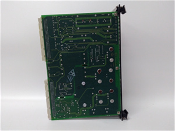
- Incoming Verification: Match the serial to the manifest. Inspect the 96-pin backplane fingers (P1/P2) for carbon tracking or burnt pins—125V input faults can scar these. Check the large filter capacitors for bulging tops (electrolytic aging).
- Power-Up Load Test: Rig on an EPBP test fixture with 125 Vdc input. Verify all output rails (+5, +/-15, +24, +70) under 50% load. Ripple on the +5V rail must be < 50mV p-p; excess noise causes CPU resets on the connected controllers (M1/M2/C).
- Isolation Check: Megger the 125V input terminals to the output grounds/chassis at 500V. Leakage must be >10 MΩ; a short here can send 125V into the 5V logic cards, destroying the rack.
- LED Logic Check: Confirm “AC/DC OK” and “+5V OK” illuminate sequentially. A lit “+5V OK” with a dim “+24V OK” often indicates a failing auxiliary winding on the inverter transformer.
- Final QC & Packaging: Clean DIN fingers with isopropanol. Bag in rigid ESD foam (it’s a tall board). Label “QC Passed – All Rails Loaded” with the date.
IS200EPSMG1AFC
Replacement Pitfall Guide
❗ G1 vs G2 Confusion: The is for Excitation Control (M1/M2/C controllers). Do not swap it with an IS200EPSMG2Axx(Regulator Control), as the backplane slot (EPBP vs ERBP) and output voltage tuning differ. Forcing a G2 into a G1 slot may result in missing +70V wetting voltage or incorrect logic levels.
❗ Redundancy Topology: In a redundant EX2100 setup, there are three independent EPSMG1s (one for M1, M2, and C sections). If replacing one, ensure the “Online Replacement” procedure is followed: transfer control via ESEL board, de-energize onlythat section’s EPDM output, swap, then re-energize. Swapping live without isolation risks backplane arcing.
❗ Seating Force: The dual connectors (P1/P2) are tight. “Half-seating” P2 while P1 is home bends the pins on the adjacentboard. Apply even pressure on the faceplate ejectors until both ends click/lock squarely.
❗ Input Polarity/Sag: While 125 Vdc is standard, site supplies can sag. If the input is below ~100V, the buck-regulator may drop out, causing “Logic Failure” on the M1 controller. Verify EPDM output voltage beforeblaming the EPSM.
❗ ESD to Fingers: The 96-pin DIN fingers are dense. Discharge to the EPBP chassis frame before insertion—critical in dry turbine halls (common in northern China winters).
Keep these in mind and you’ll cut 90% of rework time.
Compatibility Matrix & Benchmarks
- → GE IS200EPSMG1A: Direct— “AFC” is a coated/sub-revision of the base G1A. Functionally compatible, but match coating grades (C) if in corrosive environments.
- → GE EPBP (Backplane): Direct— Slides into M1, M2, or C slots of the Exciter Power Backplane.
- → GE IS200EPSMG2AEC: Incompatible— G2 is for Regulator Control (ERBP); different input ranges and output trimming.
- Conversion Efficiency: ~85% (Typical)
- Hold-Up Time: > 20 ms (At full load, bridges brief input drops)
- Isolation: 1500 Vdc (Input to Output, typical)


