
Description
Hard-Numbers: Technical Specificiations
- System Voltage Support: 125 VDC (standard plant battery)
- Bus Bar Conductivity: Copper alloy, high-current rated
- Slot Capacity: Up to 10 slots (depending on cabinet height)
- Module Compatibility: EGPA, EHPA, EDIS, EPDM, EDEX, ESEL
- Mounting Standard: 19-inch rack mount with rear DIN rail support
- Operating Temperature: -40°C to +85°C
- Environmental Coating: Conformal coated (resists salt fog and contaminants)
- Grounding Requirement: Chassis ground via M6 stud (Torque: 35 lb-in)
- Revision Designation: ACD (Lead-free / Project-specific trace routing)
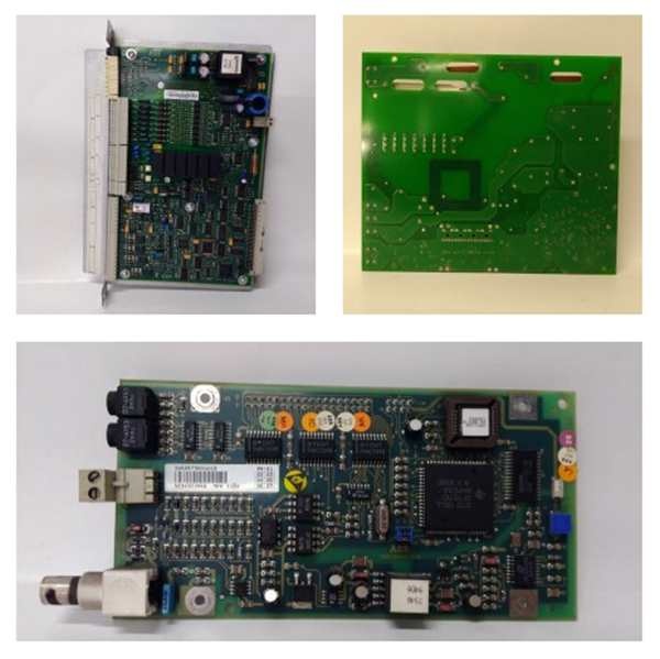
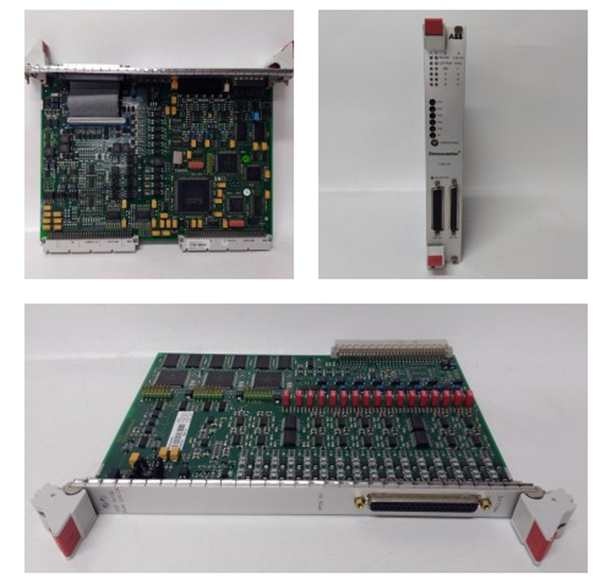
GE IS200EPBPG1ACD
The Real-World Problem It Solves
You’re troubleshooting a 9FA gas turbine that keeps tripping on “Bridge Power Loss” or “Gate Drive Communication Failure.” The old, generic backplane in the exciter cabinet has seen better days; its copper traces have micro-cracks from decades of thermal cycling, and the bus bars are oxidizing, creating intermittent high-resistance joints. You need a rock-solid foundation that can handle the massive current spikes from the thyristor bridges without flinching. This EPBP board solves that nightmare. It acts as the industrial-grade skeleton of your excitation system, ensuring every watt of 125VDC power and every nanosecond of gate pulse timing is delivered without corruption.
Where you’ll typically find it:
- EX2100 Exciter Power Cabinets: Serving as the central mounting and wiring hub for EGPA, EHPA, and EDIS modules in 9F/9HA class gas turbines.
- Heavy-Duty Hydro & Steam Turbine Exciters: Managing the dense packaging of 6+ bridge modules in high-humidity dam environments.
- Offshore Platform Turbine Skids: Providing a conformal-coated, corrosion-resistant base for excitation electronics in Class 1 Div 2 zones.
It turns a fragile, failure-prone power distribution chassis into a deterministic, high-MTBF structural backbone.
Hardware Architecture & Under-the-Hood Logic
This isn’t an active processing board; it’s a highly engineered passive distribution hub. It has no microprocessor. Its job is to provide a mechanically rigid and electrically pristine environment for the active power modules. The “ACD” suffix indicates specific trace routing and RoHS-compliant plating designed for enhanced durability in harsh environments.
- High-Current Bus Bar Distribution: Massive copper bus bars run the length of the backplane. These distribute the raw 125VDC from the EDIS module and the station battery to every single slot, minimizing voltage drop even during peak thyristor firing currents.
- Precision-Machined Module Slots: Each slot is milled to exact tolerances to accept the VME-style mounting ears of the EGPA, EHPA, and EPDM boards. This ensures perfect alignment of the rear-mounted connectors, preventing bent pins or intermittent contact.
- Signal Integrity Routing (ACD Revision): The “ACD” variant features optimized trace layouts. It separates high-noise power lines from sensitive gate pulse and communication signals, reducing crosstalk between adjacent modules.
- Thermal & Mechanical Stress Relief: The backplane is anchored to the cabinet frame at multiple points. This rigidity prevents the PCB from bowing or cracking under the weight of heavy power modules, maintaining flawless electrical continuity through thousands of thermal cycles.
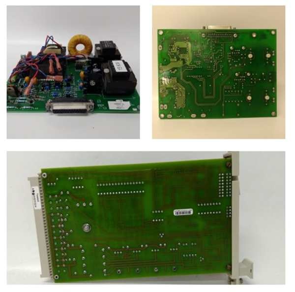
GE IS200EPBPG1ACD
Field Service Pitfalls: What Rookies Get Wrong
Ignoring the Rear Mounting Screws on Heavy Modules (EHPA/EPDM)
A rookie slides a massive EHPA (High-current Gate Pulse Amplifier) into the EPBP slot. He tightens the front faceplate screws but skips the two rear mounting screws that bolt the module to the backplane’s steel bracket. After six months of high-vibration operation, the EHPA’s PCB cracks near the connector, causing an intermittent gate drive failure that grounds the turbine.
- Field Rule: Always install the two rear mounting screws for any module weighing over 3 lbs (EHPA, EPDM). These screws prevent torque on the PCB. Torque them to 10 lb-in and use blue Loctite to prevent vibration-induced backout.
Failing to Clean the Gold-Plated Edge Connectors (Card Fingers)
A mechanic replaces a failed EGPA board. He pulls the old one, blows a little compressed air on the slot, and slams the new one in. Two weeks later, the turbine trips on “EGPA Communication Loss.” Microscopic dust particles and skin oils on the gold fingers created a high-resistance barrier, blocking the gate pulse signals.
- Quick Fix: Never insert a module into the EPBP without wiping the gold-plated edge connectors with 99% isopropyl alcohol and a lint-free swab. Inspect for scratches. If the gold plating is worn through to the nickel substrate, the module is a ticking time bomb—replace it immediately.
Improper Torquing of the Main 125VDC Bus Bar Lugs
A junior engineer is terminating the main 125VDC supply lugs onto the EPBP’s input bus bars. He uses a standard wrench and cranks them down as hard as he can. He over-torques the copper lugs, causing the soft metal to cold-flow and crack. During a peak load event, the lug shears off, creating an arc flash that destroys the entire backplane and adjacent modules.
- Field Rule: Use a calibrated torque wrench (not a screwdriver) for all bus bar terminations. Refer to the GE manual for the exact inch-pound specification (typically 25-35 lb-in for heavy lugs). Use a thin layer of anti-oxidizing paste on the copper-to-copper joints to prevent future corrosion.
Commercial Availability & Pricing Note
Please note: The listed price is for reference only and is not binding. Final pricing and terms are subject to negotiation based on current market conditions and availability.


