
Description
Hard-Numbers: Technical Specifications
- Power Supply: 5 VDC (drawn from backplane)
- Form Factor: Single-slot, double-height VME-style card
- Dimensions: 9.25 in (L) x 6.5 in (W)
- Weight: ~2 lbs (0.91 kg)
- Backplane Connector: P1 (inter-board communication)
- I/O Connector: P2 (external signal interface via EBKP backplane)
- LED Indicators: 2 total (Power LED + FPGA Status/IMOK LED)
- Operating Temperature: Industrial grade
- Mounting Style: Control rack installation with captive faceplate screws
- Jumpers/Fuses: None (fully integrated design)
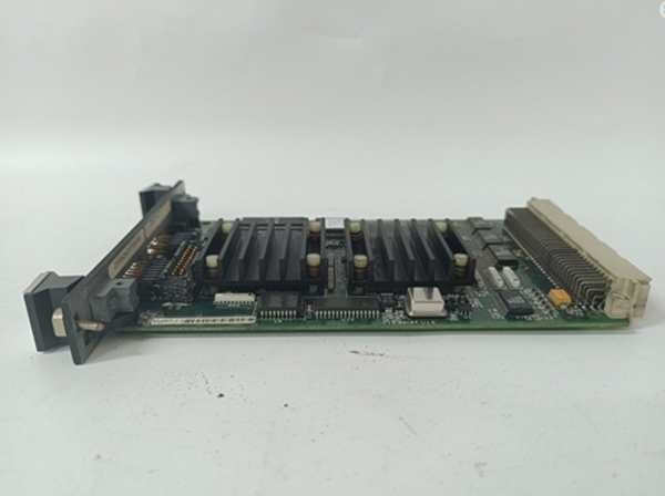
GE IS200EMIOH1A
The Real-World Problem It Solves
You’re troubleshooting a 9FA gas turbine where the excitation control system keeps throwing “De-excitation Sequence Failed” alarms. The old distributed I/O wiring is a rat’s nest of PT/CT signals, contact inputs, and relay drivers all crammed into one cabinet, creating noise crosstalk and intermittent dropouts. You need a single board that can aggregate every terminal board signal, run the de-excitation logic, and route gate pulses to the ESEL board without breaking a sweat. This EMIO board eliminates that mess. It’s the central nervous system of the EX2100 excitation control, processing ECTB/EACF/EXTB/EPCT data and firing gate pulses with deterministic precision.
Where you’ll typically find it:
- EX2100 Exciter Control Cabinets: Seated directly in the control rack, bridging all terminal boards and the ESEL/EDEX boards via the EBKP backplane
- Heavy-Duty Gas & Steam Turbine Generators: Managing contact inputs, pilot trip relays, and PT/CT signal conditioning for AVR control
- Retrofit Projects: Replacing sprawling discrete relay panels with a single VME-slot I/O hub for cleaner cabinet layouts
It turns a tangled, noise-prone I/O distribution system into a streamlined, FPGA-managed control backbone.
Hardware Architecture & Under-the-Hood Logic
This board isn’t a dumb terminal block; it’s an FPGA-driven signal aggregator with its own decision-making logic. It lives on the EX2100 control rack, acting as the master dispatcher between four terminal boards and the ESEL/EDEX downstream processors. The “H1A” suffix indicates optimized trace routing and enhanced signal integrity.
- Terminal Board Signal Aggregation: The EMIO receives signals through connector P2, which interfaces with the EBKP backplane. It pulls in PT/CT measurements from EACF, contact inputs from ECTB, breaker status from EXTB, and power control signals from EPCT—all in one consolidated stream.
- FPGA-Based Signal Processing: An onboard FPGA (Field Programmable Gate Array) processes the aggregated data in real-time. It validates contact states, scales PT/CT readings, and drives the output relay coils with deterministic timing.
- Gate Pulse Forwarding to ESEL: When the DSPX processor issues a firing command, the EMIO forwards the logic-level gate pulse signals through the backplane to the ESEL (Exciter Selector) board. From there, they cascade to the EGPA/EHPA boards in the power cabinet.
- De-excitation Sequence Initiation: The EMIO directly controls the EDEX board to initiate de-excitation sequences. When a trip is commanded, the FPGA triggers the crowbar circuit and discharges the field winding, protecting the rotor from overvoltage damage.
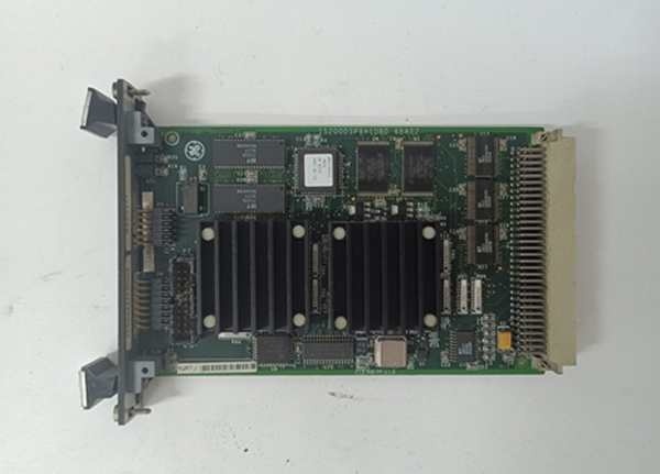
GE IS200EMIOH1A
Field Service Pitfalls: What Rookies Get Wrong
Pulling the Board Without Photographing the Faceplate Screws
A rookie rushes to replace a failed EMIO during an outage. He yanks the board out without noting the captive screw positions. When he installs the replacement, he over-tightens one corner screw, warping the faceplate and creating a poor backplane connection. The turbine powers up but throws continuous “Backplane Communication Loss” alarms.
- Field Rule: Always photograph the captive screw positions before removal. Tighten faceplate screws evenly—hand-tight plus a quarter-turn max. Uneven torque will warp the VME card frame and kill the backplane connection.
Ignoring the FPGA IMOK Status LED Behavior
A tech sees the green Power LED lit but the Status LED is off. He assumes the board is fine and moves on. Three hours into commissioning, the de-excitation sequence fails because the FPGA never initialized properly. The rotor field stays energized after a trip, cooking the windings.
- Quick Fix: Both LEDs must be lit for a healthy board. If the Power LED is on but Status (IMOK) is off, the FPGA failed to boot. Pull the board, reseat it firmly in the slot, and verify the EBKP backplane power is stable at 5VDC before declaring victory.
Assuming the EMIO Works Standalone Without EBKP
A junior engineer tries to bench-test a spare EMIO board on a workbench, connecting 5VDC to the power pins and probing the P2 connector. Nothing happens. He declares the board dead and scraps it. The reality? The EMIO requires the EBKP backplane for initialization and signal routing. It can’t operate as a standalone device.
- Field Rule: Never attempt to functionally test an EMIO outside of a live EBKP backplane environment. For bench verification, you need a full EX2100 control rack with EBKP, DSPX, and power supply. If you must verify a spare, check the Power and Status LEDs after installation in the actual control rack.
Commercial Availability & Pricing Note
Please note: The listed price is for reference only and is not binding. Final pricing and terms are subject to negotiation based on current market conditions and availability.


