

Description
Hard-Numbers: Technical Specifications
- PPT Input Voltage: 480 Vrms (50/60 Hz, ±20%)
- Transformer Secondary Output: 1.6 Vrms nominal
- Flux Coil (Air-core CT) Input: 0 to 0.8 Vrms
- Backplane Cable Length Limit: 295 ft (90 meters)
- Controller Interfaces: 3x 9-pin D-sub (M1, M2, C Controllers)
- Terminal Blocks: 4x (TB1-TB4)
- Operating Temperature: -40°C to +70°C
- Shield Grounding Distance: Within 3 inches (76mm) of entry
- Isolation Rating: 1500 VAC channel-to-chassis
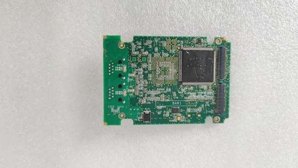
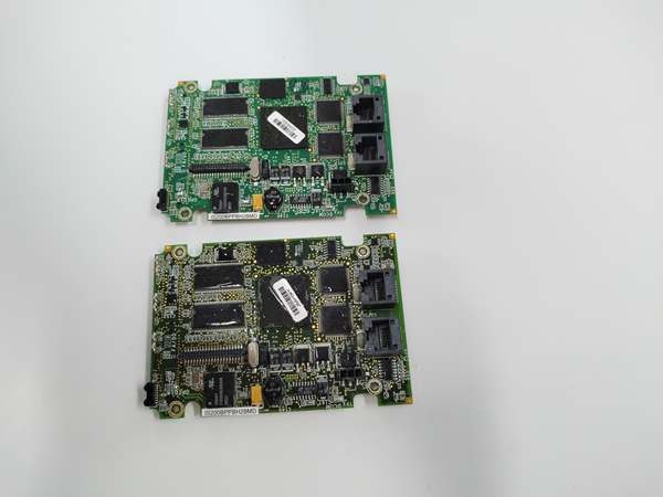
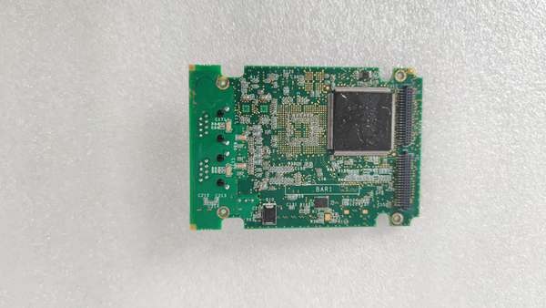
IS200BPPBH2B
The Real-World Problem It Solves
You’re knee-deep in a refinery turbine outage, and the generator is oscillating on VARs because the cheap analog meters can’t keep up with the 60Hz ripple. You need a rock-solid interface that can take 480V AC from the PPTs and millivolt-level signals from the flux coils, scrubbing the electrical hash from nearby 4160V switchgear before it hits the controllers. This EACF board is the gatekeeper. It steps down the voltage, strips the noise, and feeds clean, isolated data to the M1/M2/C controllers, preventing false trips during load rejections.
Where you’ll typically find it:
- EX2100 Exciter Auxiliary Cabinets: Bridging the gap between field potential transformers (PPTs) and the main control rack
- Heavy-Duty Steam Turbine Generators: Providing real-time feedback for Automatic Voltage Regulators (AVR)
- Refinery/Syn-Fuel Cogen Units: Operating in Class 1 Div 2 zones where electrical noise and vibration are constant threats
It turns a chaotic, high-voltage feedback loop into a deterministic, interference-free signal chain.
Hardware Architecture & Under-the-Hood Logic
This board doesn’t house a microprocessor. It is a passive, hardened signal interface designed to survive the brutal electrical environment of a power plant. Its sole job is to protect the incredibly expensive M1/M2 controllers from high-voltage transients and field wiring faults.
- Voltage Step-Down & Galvanic Isolation: The 480V PPT inputs hit three onboard step-down transformers. These knock the voltage down to a safe 1.6Vrms while providing complete galvanic isolation between the high-voltage field and the 24V control logic.
- Flux Coil Signal Conditioning: The incredibly weak 0-0.8Vrms signal from the air-core current transformer (Flux Coil) passes through an onboard RC filter network. This strips out the high-frequency switching noise from nearby thyristor bridges before the signal ever reaches the controller.
- Signal Fan-Out Logic: The conditioned signals are duplicated across three 9-pin D-sub connectors. This allows one set of field wiring to simultaneously feed the primary M1 controller, the redundant M2 controller, and the C controller without splitting the signal strength.
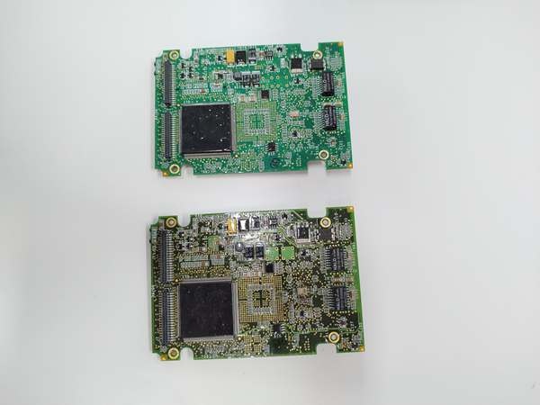
IS200BPPBH2B
Field Service Pitfalls: What Rookies Get Wrong
Ignoring the 3-Inch Shield Grounding Rule
A rookie terminates the shielded twisted pair from the flux coil and ties the shield to the nearest convenient ground point ten feet away. The turbine runs fine until a 13.8kV breaker closes on a parallel bus. The induced EMI travels along the shield and spikes the M1 controller, causing a nuisance trip on “Field Overcurrent.”
- Field Rule: Ground the cable shield within 3 inches (76mm) of the terminal block. Use a 360-degree clamp or a star washer to ensure a low-impedance connection to the board’s chassis ground lug. Never let the shield float or run it long distances.
Swapping a Standard Board for a “ZZ” Project Build
You pull a smoked IS200EBACG1AZZ and grab a generic IS200EBACG1A from the warehouse. It bolts in perfectly, but the turbine refuses to synchronize. The “ZZ” hardware has custom burden resistors and gain settings specific to this refinery’s 480V PPT configuration. The standard card’s default settings are completely out of whack.
- Quick Fix: Photograph the resistor and jumper configuration of the failed board before removing it. If the P/N ends in “ZZ”, you mustsource that exact custom revision. A standard spare will not have the correct burden values or I/O mapping for the site-specific application.
Exceeding the 90-Meter Backplane Cable Limit
During a civil works upgrade, the exciter cabinet was moved 400 feet away from the main control room. The tech runs a long coaxial cable to connect the EACF to the M1 controller. The signal degrades over the distance, and the controller frequently reports “Feedback Loss” during high-vibration events.
- Field Rule: The cable length between the EACF and the M1/M2/C controllers must not exceed 90 meters (295 ft). If you need to go further, install a fiber-optic media converter at the 90m mark or relocate the control rack. Do not try to stretch the limit; cable capacitance will murder your signal integrity.
Commercial Availability & Pricing Note
Please note: The listed price is for reference only and is not binding. Final pricing and terms are subject to negotiation based on current market conditions and availability.


