
Description
Hard-Numbers: Technical Specifications
- Gate Drive Supply: +15V / -7.5V DC
- Frame Rating: 250 Frame
- IGBT Module: Powerex CM400HA-28H (per drive)
- Modules Per Drive: 3 (one upper + one lower phase leg)
- IGBT Count: 2 per board
- Operating Temperature: 0°C to +60°C
- Status Indicators: 4 LEDs for IGBT state and fault reporting
- Compatibility: Mark VI Innovation series control systems
- Test Points: None
- Onboard Fuses: None
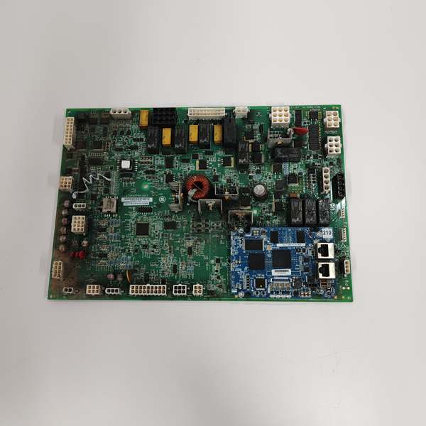
GE IS200AEPAH1BKE
The Real-World Problem It Solves
You’re working a 500MW combined cycle plant where the old relay-based gate drive system keeps misfiring, causing IGBT overheating and unplanned turbine trips. You need a rugged, purpose-built interface that eliminates control rack to power device wiring complexity and prevents short-circuit damage to expensive IGBTs. This DAMC board solves that problem. It provides isolated, amplified gate drive signals directly to the IGBT pins, with built-in status monitoring that catches faults before they cascade into full-blown system failures.
Where you’ll typically find it:
- 250-frame power bridge systems in 9F/9HA class gas turbines for excitation and drive control
- Industrial variable frequency drive (VFD) systems for large 4160V induction motors in refinery/chemical plants
- Retrofit projects converting legacy relay-based gate drive systems to Mark VI-compatible solid-state control
It turns a unreliable, fault-prone gate drive setup into a deterministic, monitored control interface that keeps your power electronics running without catastrophic failures.
Hardware Architecture & Under-the-Hood Logic
This is not a general-purpose I/O card; it’s a dedicated high-current gate driver interface designed to survive the harsh electrical environment of power bridge cabinets. It operates on the Mark VI backplane, bridging the gap between low-voltage control signals and high-voltage power switching devices.
- Control Rack Interface: The board connects to the Mark VI controller via the IS200CABPG1B backplane, receiving digital gate drive commands and feedback requests from the main CPU.
- Signal Amplification Stage: Raw 3.3V gate drive commands from the controller are buffered and amplified to the required +15V/-7.5V levels needed to fully turn on/off the Powerex CM400HA-28H IGBT modules.
- Direct IGBT Pin Connection: The board connects directly to the IGBT gate, collector, and emitter pins via heavy-duty cabling, eliminating intermediate terminal blocks that can loosen under vibration and cause arc faults.
- Status Monitoring & Fault Reporting: Four onboard LEDs continuously report IGBT state (on/off), collector-emitter voltage, gate drive integrity, and overcurrent conditions. Fault states are immediately reported back to the Mark VI controller for alarm and trip logic execution.
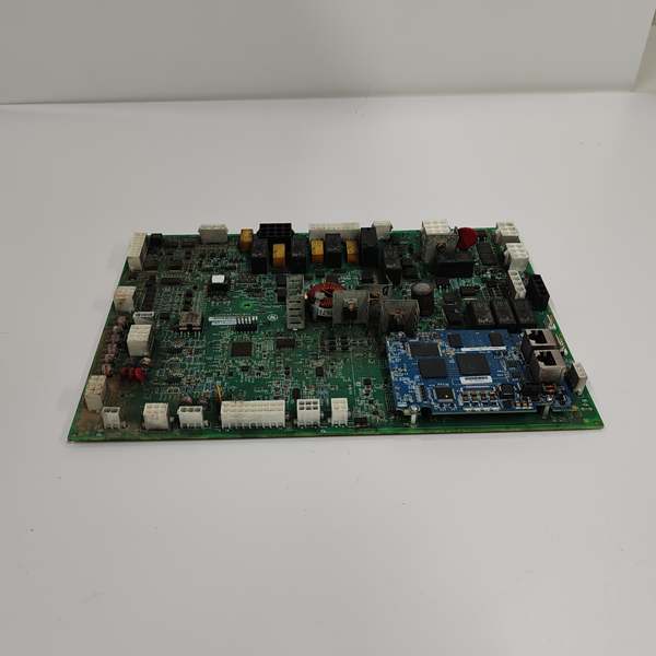
GE IS200AEPAH1BKE
Field Service Pitfalls: What Rookies Get Wrong
Mismatching IGBT Module Part Numbers
A rookie replaces a failed IGBT module with a generic CM400HA-24H instead of the required CM400HA-28H specified for the IS200DAMCG1A. The lower voltage rating causes the IGBT to fail catastrophically during a full-load transient, taking out the entire power bridge.
- Field Rule: Always verify the exact IGBT part number stamped on the module before installation. The IS200DAMCG1A is specifically tuned for the CM400HA-28H’s gate capacitance and voltage ratings. Never substitute with compatible-but-different parts.
Reversing Gate Drive Power Supply Polarity
A technician reconnects the +15V/-7.5V gate drive power supply backwards during a maintenance outage. The reversed polarity destroys the gate driver circuitry on the DAMC board instantly, requiring a full board replacement and delaying plant startup by 48 hours.
- Quick Fix: Before energizing the gate drive power supply, use a multimeter to verify the polarity at the board’s input terminals. The +15V terminal should show +15V relative to ground, and the -7.5V terminal should show -7.5V relative to ground. Label all power supply cables clearly with polarity markings.
Ignoring IGBT Pin Clearance Requirements
A tech installs the IGBT modules too close to the DAMC board, leaving less than 25mm of clearance between the IGBT case and the board’s sensitive gate drive components. Heat rising from the IGBTs during full load operation overheats the DAMC board, causing intermittent gate drive failures and turbine trips.
- Field Rule: Maintain a minimum 50mm clearance between the DAMC board and all IGBT modules. Install the board in a well-ventilated location, and consider adding a dedicated 24VDC cooling fan if the cabinet ambient temperature exceeds 40°C during peak load operation.
Commercial Availability & Pricing Note
Please note: The listed price is for reference only and is not binding. Final pricing and terms are subject to negotiation based on current market conditions and availability.


