
Description
Hard-Numbers: Technical Specifications
- Analog I/O: 8 analog inputs, 1 analog output.
- Encoder Inputs: 1 incremental encoder, 1 absolute encoder.
- Discrete I/O: 20 discrete inputs, 1 discrete output.
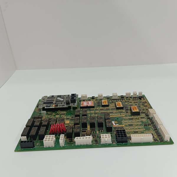
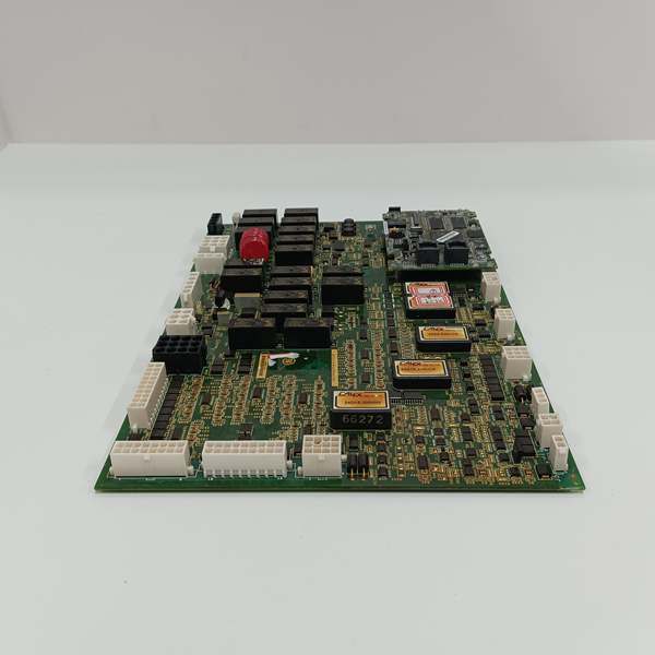
- Relay Outputs: 8 onboard relays + 12 general relays on PCB.
- Brake Control: 1 dedicated brake control output.
- Communication Ports: 2 RS-485 interfaces.
- Surge Protection: 6 metal oxide varistors (MOVs) in single line configuration.
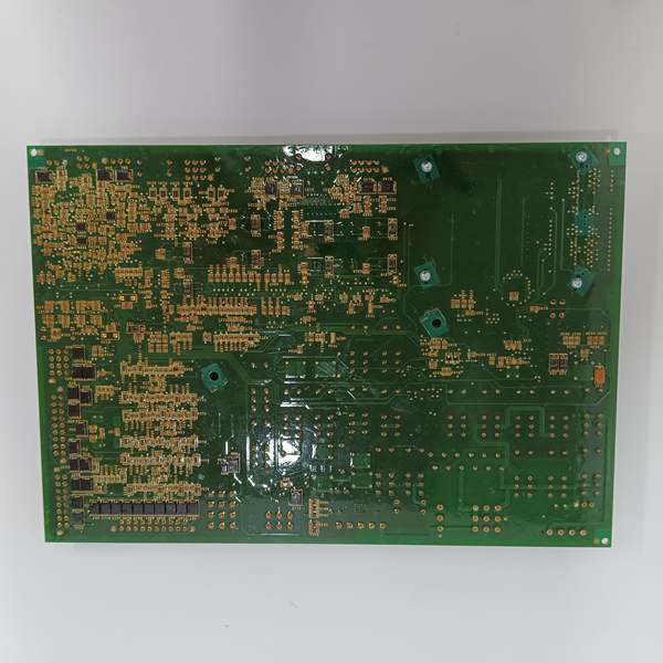
- Environmental Protection: Mil-spec or industrial-grade conformal coating over all traces and components.
- Operating Temperature: 0°C to +60°C.
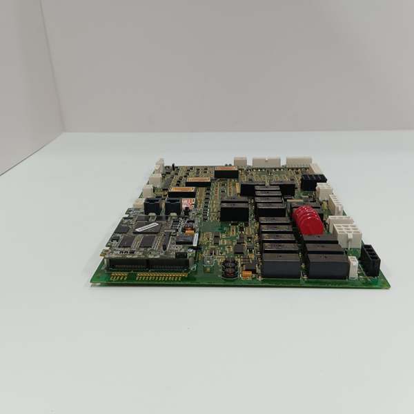
- Connectivity: 2 male pin connectors (upper-left) for main processor; 17 vertical female pin connectors (2-20 pins).
- Status Indicators: 2 operational LEDs on left edge.
GE IS200AEPAH1ACB
The Real-World Problem It Solves
You’re staring down a turbine in the North Sea or the Arizona desert. Salt spray, 100% humidity, and sand are eating your electronics alive. Standard control boards corrode, throw false encoder errors, and trip the turbine offline. This board is the heavy artillery. The ‘ADC’ suffix isn’t just a letter; it’s a promise of premium-grade passives, tighter tolerance ICs, and a military-spec conformal coating that laughs at moisture and dust.
Where you’ll typically find it:
- Offshore Wind Farms: Battling salt fog and constant 100% humidity in nacelles 50 miles from shore.
- Desert Solar/Wind Hybrids: Surviving dust storms and 120°F+ ambient temperatures without breaking a sweat.
- Repowering Projects: Upgrading older turbines in corrosive coastal regions where standard AEPA boards were failing every 18 months.
It turns a hostile environment into just another Tuesday afternoon for your control system.
Hardware Architecture & Under-the-Hood Logic
This isn’t your average PCB. It’s a localized, hardened interface designed to take the beating of the elements so the main Mark VIe controller doesn’t have to. The ‘ADC’ revision uses components selected for maximum mean time between failures (MTBF).
- Processor Interface: Two robust male pin connectors in the upper left corner provide a high-speed, vibration-resistant data highway to the main Mark VIe processor. This keeps the critical pitch setpoint commands separate from the noisy sensor world.
- Feedback Conditioning: The onboard amplifiers are premium-grade, filtering out the electrical hash from 500kW pitch motors. They deliver rock-solid sine/cosine signals from the absolute and incremental encoders, preventing the catastrophic overspeed that comes from a missed position reading.
- Actuator Drive Logic: Eight relay outputs and one discrete output act as the muscle. They energize the hydraulic solenoid valves or electric motor contactors that physically turn the blades. The dedicated brake control output is a fail-safe, feathering the blades to a safe position if the processor has a watchdog timeout.
- Environmental Fortification: The star of the show is the thick, uniform conformal coating blanketing every trace and component. Beneath that armor are six MOVs in a single line, clamping lightning-induced transients. Together, they create a nearly indestructible interface for the blade pitch system.
IS200AEPAH1ACB
Field Service Pitfalls: What Rookies Get Wrong
Destroying the Conformal Coating During Cleaning
A rookie grabs a solvent-soaked rag to wipe off grime from the nacelle. The solvent dissolves the specialized conformal coating, exposing the bare copper traces underneath to immediate corrosion from the salt air.
- Field Rule: Never use solvents like acetone or alcohol on a conformal-coated board. If it’s dirty, blow it off with dry, oil-free compressed air. If you must clean it, use a dry microfiber cloth. Once the coating is breached, the board’s days are numbered.
Mismatching Encoder Supply Voltages
You wire in a brand-new 24VDC absolute encoder without checking the JP1 supply voltage jumper. The board is configured for 5VDC by default, and the encoder burns out instantly.
- Quick Fix: Locate the JP1 jumper block near the encoder connectors before applying power. Set it explicitly for 5V or 24V to match your field device. Always verify with a multimeter at the connector pins before plugging in the encoder.
Losing the C-Shaped HW1 Metal Housing
During a frantic troubleshooting session, you pull the board and toss the unique C-shaped metal housing (marked HW1) aside. You reinstall the naked PCB. Within weeks, vibration from the gearbox cracks the board around the pin connectors, and you’ve got an intermittent pitch control fault that will take days to trace.
- Field Rule: Always reinstall the C-shaped metal housing (HW1) using the factory standoff screws. That housing isn’t just for looks; it’s the structural backbone of the board and an EMI shield. If you lose it, order a replacement immediately. Do not operate the turbine without it.
Ignoring the MOVs After a Lightning Event
A nearby lightning strike causes a momentary comms glitch. The turbine keeps running, so you figure everything is fine. You don’t know that one of the six MOVs has failed shorted. Two weeks later, a second strike hits, the shorted MOV creates a dead short, blows the 24VDC fuse, and causes a full turbine trip.
- Field Rule: After any lightning storm, perform a visual and multimeter inspection of the six MOVs. A healthy MOV will read megaohms. A failed one will read near zero ohms. Replace the entire board if you find even one compromised MOV.
Please note: The listed price is for reference only and is not binding. Final pricing and terms are subject to negotiation based on current market conditions and availability.


