
Description
Hard-Numbers: Technical Specifications
- Analog Input Channels: 8 differential input channels.
- Supported Signal Types: 4-20mA, 0-10V, Thermocouple (J/K/T/E/R/S/B), and RTD (Pt100/Cu50).
- Relay Output Channels: Up to 12 relay channels (grouped on the board).
- Isolation Rating: 1000V AC channel-to-channel; 2500V AC module-to-system bus.
- Sampling Accuracy: ±0.05% of full-scale (4-20mA); ±0.2°C (Thermocouple).
- Sampling Rate: 10 ms per channel (configurable down to 5ms/channel).
- Common Mode Rejection Ratio (CMRR): ≥120 dB at 50/60Hz.
- Power Supply: 24V DC ±10% (sourced from the Mark VIe VME rack backplane).
- Power Consumption: ≤ 8 Watts.
- Operating Temperature: -30°C to +65°C (-22°F to +149°F).
- Mounting: 13-slot or 21-slot VME rack system; supports Hot-Swap (RIUP).
- Cold Junction Compensation: Integrated, ±0.1°C accuracy.
GE IS200AEAAH2B
The Real-World Problem It Solves
Trying to route dozens of analog sensor wires and relay control lines directly into a standard I/O processor card creates a cabling nightmare and a massive single point of failure. This terminal board consolidates the chaos, acting as a rugged, high-density patch bay that isolates the delicate processor from the harsh realities of field wiring.
Where you’ll typically find it:
- Wind Turbine Nacelles: Managing the dense bundle of signals from pitch motors, vibration sensors, and nacelle anemometers.
- Balance of Plant (BOP) Skids: Interfacing with pumps, valves, and local transmitters scattered across a sprawling plant site.
- Retrofit Projects: Replacing obsolete terminal strips in legacy Mark VI racks with a modern, integrated I/O fork board.
It turns a tangled web of field wires into a single, manageable interface point.
Hardware Architecture & Under-the-Hood Logic
This isn’t a passive wire nut; it’s a buffered signal conditioning hub with its own local processing logic. It sits between the chaotic field world and the pristine digital world of the Mark VIe controller.
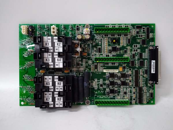
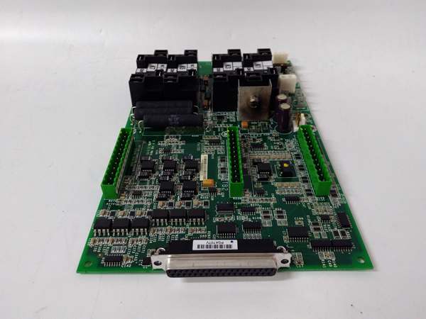
- Signal Conditioning & Buffering: Raw analog signals pass through precision wire-wound resistors and filter capacitors to eliminate electrical noise before hitting the ADCs. The integrated heat sinks manage thermal load during continuous operation.
- Relay Drive Logic: The grouped relays are driven by dedicated driver ICs. They act as the heavy lifters, switching 24VDC or 125VAC loads (like solenoid valves or alarm horns) without back-feeding noise into the sensitive analog measurement circuits.
- Grid Fork Distribution: The three vertical terminal strips (36 pins total) are internally routed to distribute power, grounds, and signal commons efficiently. This layout minimizes the loop area of your field wiring, drastically cutting down on inductive coupling noise.
- Backplane Communication: Processed analog data and relay statuses are packetized and pushed across the VME backplane to the main Mark VIe controllers (e.g., IS215UCVEH2A) via the high-speed IONet protocol.
GE IS200AEAAH2B
Field Service Pitfalls: What Rookies Get Wrong
Starving Relays with Undersized Wire
Rookies land the 24VDC power wire for the relays using the same 22 AWG wire meant for 4-20mA signals. When multiple relays energize simultaneously, the voltage drop across that skinny wire causes the relays to chatter or fail to pull in.
- Field Rule: Use minimum 18 AWG (0.75 mm²) stranded copper wire for the 24VDC power feed to the terminal board. Verify the voltage at the terminal strip under load; it should never drop below 20VDC.
Mixing Thermocouple and 4-20mA Commons
You wire a Type K thermocouple and a 4-20mA pressure transmitter into the same terminal strip. Because the commons aren’t perfectly isolated, the DC current loop induces a voltage offset on the thermocouple circuit, throwing your temperature readings off by 5 degrees.
- Quick Fix: Physically separate your signal types. Use one terminal strip exclusively for thermocouples/RTDs and another for 4-20mA/0-10V signals. Keep your low-voltage signal commons tied to the chassis ground at a single point only.
Blindly Swapping H1A for H3A Without Checking Firmware
A rookie pulls a dead IS200AEADH1A off the shelf and jams in an IS200AEADH3A. The hardware fits, but the controller throws a “Hardware Mismatch” fault because the internal silicon stepping and register map changed between revisions.
- Field Rule: Before swapping revisions, check the Mark VIe ControlST or ToolboxST configuration. If the software expects an H1A, you may need to update the controller’s firmware or manually import the new hardware definition file for the H3A.
Please note: The listed price is for reference only and is not binding. Final pricing and terms are subject to negotiation based on current market conditions and availability.


