

Description
Hard-Numbers: Technical Specifications
- Drive Type: Multi-Axis Servo Amplifier
- Number of Axes: Up to 2 axes per module (depends on specific variant)
- Motor Type: Permanent Magnet Brushless AC Servo
- Power Rating: 0.5 kW to 5 kW per axis (varies by model variant)
- Input Voltage: 380-480VAC, 3-phase, 50/60 Hz (ABAC variant)
- Input Current: 6A per axis typical at 400VAC
- Continuous Current: 3A per axis continuous (depends on motor)
- Peak Current: 9A per axis peak (1-3 seconds)
- Bus Voltage: 600VDC typical (rectified from AC mains)
- Output Frequency: 0-300 Hz (PWM frequency 4 kHz / 8 kHz selectable)
- Control Mode: Position, Velocity, Torque Control
- Feedback: Resolver, EnDat, or Hiperface DSL (depends on variant)
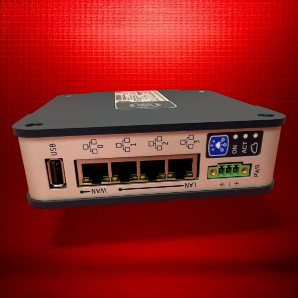
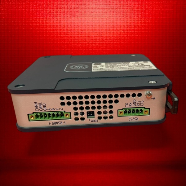
- Communication: SERCOS III (fiber ring), PROFINET IO, or EtherNet/IP (depends on configuration)
- Regeneration: Built-in braking resistor (external resistor available for high regen loads)
- Protection: Overcurrent, overvoltage, undervoltage, overtemperature, ground fault
- Operating Temperature: 0°C to 50°C (32°F to 122°F)
- Storage Temperature: -20°C to 70°C (-4°F to 158°F)
- Enclosure Rating: IP20 (requires NEMA 12/4X enclosure)
- Cooling: Forced air (integrated fan)
- Mounting: Panel mount (vertical orientation required)
- Certifications: UL 508C, CE, IEC 61800-5-1

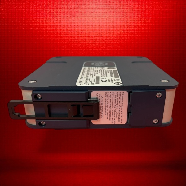
GE ICMFA000000-ABAC
The Real-World Problem It Solves
Multi-axis motion requires precise synchronization. The ICMFA000000-ABAC integrates multiple servo axes in a single drive, eliminating cabling complexity and ensuring tight axis coordination through internal motion bus. Your packaging line 终止s and starts exactly when it should, with minimal wiring between drives.
Where you’ll typically find it:
- Packaging machine gantry systems requiring coordinated X-Y motion
- Printing presses with multiple web tension control axes
- Material handling robots with synchronized conveyor tracking
Bottom line: It gives you multi-axis coordination in a compact package with reduced wiring and internal synchronization.
Hardware Architecture & Under-the-Hood Logic
The PACMotion servo drive uses a high-performance DSP (Digital Signal Processor) for real-time motor control. Each axis has its own current loop, velocity loop, and position loop running at independent update rates. The drive includes a power section with IGBT inverter bridges converting DC bus voltage to 3-phase PWM output. The feedback interface reads position and velocity from the motor encoder (resolver or digital feedback). The communication module manages external network connections (SERCOS III fiber, PROFINET, or EtherNet/IP) and exchanges motion commands with the PLC or motion controller. Regeneration energy during deceleration is dissipated through built-in braking resistors or fed back to the DC bus (with shared bus option). The drive firmware executes complex motion profiles including electronic gearing, camming, and interpolation.
Internal signal flow:
- AC mains (380-480V) enters drive; passes through EMI filter and line reactor
- 3-phase bridge rectifier converts AC to DC bus voltage (~600VDC)
- DC bus capacitor banks filter ripple and store energy
- IGBT inverter bridges chop DC into variable frequency 3-phase PWM output per axis
- Current sense resistors monitor phase currents for current loop control
- Motor encoder feedback connects to feedback interface (resolver/digital)
- Position and velocity data feed into motion control DSP
- DSP executes cascaded control loops (current → velocity → position)
- External network (SERCOS/PROFINET/EtherNet/IP) provides motion commands
- Drive updates motion status and position feedback to external controller
- During deceleration, regen energy dissipates through braking resistor
- Internal monitoring circuits detect faults and trigger protection events
GE ICMFA000000-ABAC
Field Service Pitfalls: What Rookies Get Wrong
Incorrect motor pairing creates overheating and torque lossThe ICMFA000000-ABAC supports multiple motor variants, but inductance and resistance parameters must match. I’ve seen technicians pair the wrong motor with the drive, causing the drive to fault on overcurrent or the motor to overheat due to mismatched parameters.
- Field Rule: Verify motor nameplate matches drive-supported motor series. Download correct motor parameters into the drive (or PACMotion software) based on motor part number. Run autotune for each axis during commissioning to calibrate current and velocity loops. Document motor-to-drive pairing in your asset management system.
Improper grounding causes erratic encoder signalsServo drives are sensitive to ground loops and EMI. I’ve seen random encoder errors and position drift because technicians tied the shield to ground at both ends or bonded the drive incorrectly.
- Field Rule: Ground the motor cable shield at the drive end only using the PE terminal. Use the correct shield clamp connector provided with the drive. For resolver feedback, use twisted pair shielded cable with shield grounded at drive end. Measure ground potential between drive PE and motor ground—should be less than 1VAC.
Using undersized braking resistor causes regen faultsThe built-in braking resistor is rated for intermittent duty. I’ve seen applications with frequent 终止s and high inertia loads trip the drive on overvoltage because the resistor can’t dissipate regen energy fast enough.
- Field Rule: Calculate regen energy based on your worst-case deceleration profile. If the built-in resistor is insufficient, install an external braking resistor rated for your regen duty cycle. Configure the drive for external resistor mode and set the regen threshold appropriately. Monitor bus voltage during commissioning on rapid deceleration—it should stay below 750VDC.
Skipping autotuning creates vibration and poor trackingThe drive’s current and velocity loop parameters are factory-set for typical motors, but your application has unique inertia and load characteristics. I’ve seen technicians skip autotuning, resulting in audible vibration, poor tracking, and unstable motion.
- Field Rule: Always run autotune for each axis after mechanical integration. The autotune procedure identifies motor inductance, resistance, and load inertia, and calculates optimal PID gains. Perform autotune at typical operating conditions (load connected, normal speed range). Fine-tune after autotune if necessary—adjust gains in small increments and verify stability.
Ignoring encoder alignment creates position errorsThe electrical zero position must align with mechanical zero for accurate positioning. I’ve seen technicians skip homing procedures or set the wrong encoder offset, causing axes to move to the wrong position on startup.
- Field Rule: Perform homing sequence after any mechanical change or encoder replacement. Configure the homing routine in your application (single-turn homing, multiple-turn homing, or homing with external switches). Verify zero position matches the mechanical reference. Document homing procedure and offset values in your maintenance procedures.
Daisy-chaining DC bus for shared bus without proper isolationThe PACMotion system supports shared DC bus configuration for energy sharing between axes. I’ve seen technicians daisy-chain DC bus connections without using proper isolation or monitoring, creating potential single-point failures and fault propagation.
- Field Rule: Use GE-approved DC bus link modules for shared bus configurations. Install fuses or circuit breakers on each DC bus branch for isolation. Monitor bus voltage on each drive during commissioning to verify stable operation. If one drive faults, the isolation prevents bus collapse and protects other axes. Never hardwire DC bus connections without proper protection and monitoring.
Commercial Availability & Pricing Note
Please note: The listed price is for reference only and is not binding. Final pricing and terms are subject to negotiation based to current market conditions and availability.


