
Description
Hard-Numbers: Technical Specifications
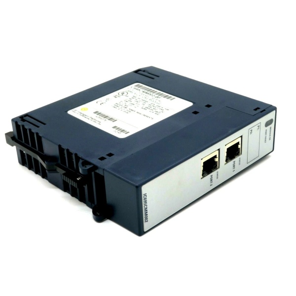
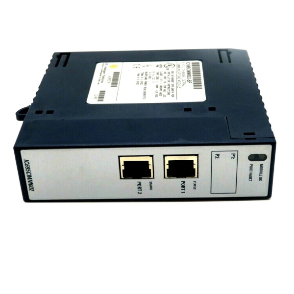
- Port Count: 2 independent isolated serial ports
- Connector Type: RJ-45 female (custom pinout – NOT standard Modbus)
- Supported Protocols: Modbus Master, Modbus Slave, DNP3 Master, DNP3 Slave, CCM Slave, Serial I/O
- Serial Interfaces: RS-232, RS-485/422 (4-wire full duplex or 2-wire half duplex)
- Baud Rates: 1200, 2400, 4800, 9600, 19.2K, 38.4K, 57.6K, 115.2K
- Data Format: 7 or 8 data bits; 1 or 2 终止 bits; Even/Odd/None parity
- Isolation Rating: Port-to-backplane: 250VAC continuous, 1500VAC for 1 minute; Port-to-port: 500VDC continuous
- Power Draw: 0.7A @ 3.3VDC, 0.115A @ 5.0VDC
- Operating Temperature: 0°C to +60°C
- Max Overvoltage: ±25 VDC
- Input Impedance: RS-485/422: >96 kΩ; RS-232: 3-7 kΩ
- Termination: Built-in 120Ω (selectable) or external
- LED Indicators: Module OK, Port Fault, Port Status (P1, P2)
-

GE IC695CMU310
-
The Real-World Problem It Solves
This module gives you two isolated serial ports that can talk multiple industrial protocols without buying separate gateway hardware. You get Modbus, DNP3, and CCM support in one module that plugs directly into your RX3i backplane, eliminating external converters and their associated failure points.
Where you’ll typically find it:
- Water treatment plants reading flow meters and chemical dosing equipment via Modbus RTU
- Power generation substations communicating with RTUs and relays over DNP3
- Manufacturing lines interfacing with barcode scanners, weigh scales, and legacy PLCs
- Oil & gas facilities bridging RX3i controllers to Series 90-30 equipment
Bottom line: It’s your workhorse serial communications module for RX3i systems needing reliable, isolated multi-protocol connectivity without external hardware.
Hardware Architecture & Under-the-Hood Logic
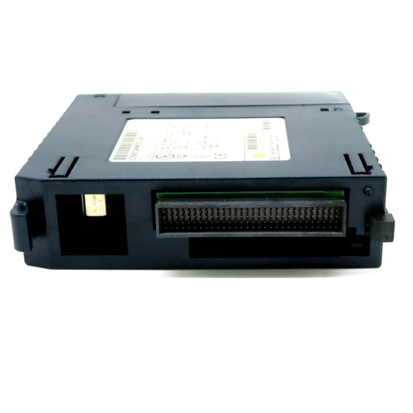
The IC695CMM002 is a smart module with its own microcontroller handling protocol stacks on each port. Each channel has dedicated isolation hardware protecting your backplane from ground loops and voltage spikes, with dual-port RAM for high-speed data exchange to the CPU.
Signal flow breakdown:
- External device connects via RJ-45 (custom pinout – watch your cables)
- Signal hits optical isolation barrier before touching any logic
- Port microcontroller processes per-protocol configuration stored in flash
- Modbus Master initiates polling cycles or Slave responds to master queries
- DNP3 handles its protocol stack with optional timestamp sync (CPU firmware 5.00+)
- CCM Slave responds to Communications Command Module queries
- Serial I/O passes raw data with optional SPL scripting (firmware 1.30+)
- Data crosses backplane through mapped memory references (%I/%Q/%AI/%AQ)
- Watchdog timer, RAM, and flash status monitored continuously
- LED indicators updated real-time for fault diagnosis
Protocol lockout mechanism: DNP3 takes over the entire module. If one port runs DNP3, all ports must run DNP3—no mixing with Modbus or CCM on the same card.
GE IC695CMU310
Field Service Pitfalls: What Rookies Get Wrong
Standard Modbus Cable Mismatch
Techs grab off-the-shelf Modbus cables and wonder why there’s no comms. This module uses a custom RJ-45 pinout that’s completely different from standard Modbus wiring. You’ll wire straight into shorts or open circuits if you use stock cables.
Field Rule: Build your own cables using the pin assignments in the manual. Pin 1 is RTS/RFR, not TX+. No shield pin exists on the connector—run shields to the backplane ground bar via the M3 tapped holes.
DNP3 Protocol Exclusivity
Engineers configure Port 1 as Modbus Master and Port 2 as DNP3 Slave, expecting both protocols to work. Firmware locks the entire module to DNP3 if any port uses it. You’re not mixing protocols on one card.
Field Rule: Plan your protocol distribution per module. If you need DNP3, dedicate that module to DNP3 only. Use a separate IC695CMM002 for Modbus/CCM operations.
RS-485 Termination Neglect
Installers daisy-chain devices without enabling termination at the endpoints. Signal reflections cause intermittent comms that drive you crazy during troubleshooting. The module defaults to no termination—you have to enable it.
Field Rule: If this module sits at either end of your RS-485 trunk, enable the internal 120Ω termination. Pull the faceplate, move the appropriate jumper (upper for 4-wire full duplex, lower for 2-wire half duplex). Don’t rely on external termination unless you know exactly what you’re doing.
Memory Boundary Alignment in Modbus Slave
Programmers map Modbus coils to %Q memory starting at random addresses like %Q00007. The module rejects mapping that doesn’t align on byte boundaries, and your slave won’t respond.
Field Rule: All Modbus slave mappings must start on byte boundaries: %Q00001, %Q00009, %Q00017, etc. If the address doesn’t end in 1 or 9 (for %Q/%I), you’re doing it wrong.
Firmware-Software Version Mismatch
You upgrade the module to firmware 1.32 for half-duplex support but leave Proficy Machine Edition at 5.6. You can’t configure the new features and waste the upgrade effort.
Field Rule: Match firmware to programming software:
- Firmware 1.10+ CCM: Machine Edition 5.6 SIM 6+
- Firmware 1.20+ DNP3: Machine Edition 5.6 SIM 10+
- Firmware 1.30+ SPL: Machine Edition 5.8 SIM 2+
- Firmware 1.32+ Half Duplex: Machine Edition 5.9 SP1 SIM 6+
First CCM Query After Power Cycle
After reconfiguring or hot-swapping the module, the first Read Scratchpad command from a CCM Master gets rejected. Techs think the card is dead and swap it out unnecessarily.
Field Rule: This is documented behavior, not a fault. After configuration changes or hot-swap, the module rejects the first CCM query. Send a second query—it will work fine every time.
DNP3 Multiple Object Read Failure
Developers try to read %I and %AI memory in a single DNP3 request. The port processes only the first object group and ignores the rest. You’re not getting all your data.
Field Rule: Split the reads into separate exchanges. First exchange for %I (discrete inputs), second exchange for %AI (analog inputs). One object group per request—that’s the limit.
SPL Script String Length Overflow
Programmers load SPL scripts with literal strings over 127 characters. The module rejects the file with error 61, and techs waste hours debugging valid code.
Field Rule: Keep literal strings at 127 characters or less. If you need longer strings, concatenate them in code. The firmware doesn’t handle oversized string literals—it’s a hard limit, not a bug.
RS-232 Hardware Handshake Mismatch
Technicians enable RTS/CTS hardware flow control in software but the connected device doesn’t support it. Communication hangs because the module is waiting for CTS that never comes.
Field Rule: Default to “None” for flow control unless you know for a fact the external device requires handshaking. Most industrial serial devices work fine without RTS/CTS. Only enable it when you’ve verified the device expects it.
Missing Shield Ground Connection
Installers terminate cable shields at the RJ-45 connector but that pin doesn’t exist. You’ve got floating shields in high-noise cabinets and EMI-induced communication errors.
Field Rule: The RJ-45 has no shield pin. Run the cable shield to the backplane ground bar using the M3 tapped holes along the bottom of the chassis. Don’t leave shields floating—ground them properly.
Quick Fix: Use shielded cable for all RS-485 runs. CE certification requires it, and field experience shows it prevents 90% of noise-related comm failures.
Module Count Limit in Backplane
System designers try to cram more than six serial communication modules into the main CPU backplane. The backplane can’t supply the current and you’ll see random module faults.
Field Rule: Maximum six IC695CMM002/004 modules in the main RX3i backplane. That’s 8 to 24 serial ports total. If you need more, expand into a remote backplane or use serial-to-Ethernet converters.
Commercial Availability & Pricing Note
Please note: The listed price is for reference only and is not binding. Final pricing and terms are subject to negotiation based on current market conditions and availability.


