
Description
Hard-Numbers: Technical Specifications
- Number of Inputs: 8 points (each individually isolated)
- Rated Voltage: 240V AC (50/60 Hz)
- Input Voltage Range: 0 to 264V AC
- On-State Voltage: 148V AC to 264V AC (guaranteed ON)
- Off-State Voltage: 0V to 40V AC (guaranteed OFF)
- Input Current: 15 mA typical at rated voltage
- On-State Current: 6 mA minimum
- Off-State Current: 2.2 mA maximum
- Response Time: 30ms ON / 45ms OFF (maximum)
- Isolation Rating: 250V AC continuous (field to backplane, point-to-point); 1500V AC for 60 seconds (field to frame)
- Backplane Power Draw: 60 mA @ 5V DC (all inputs ON)
- Operating Temperature: 0°C to 60°C (32°F to 140°F)
- Input Circuit Type: Reactive (resistor/capacitor filtering)
- LED Indicators: 8 green LEDs (one per input point)
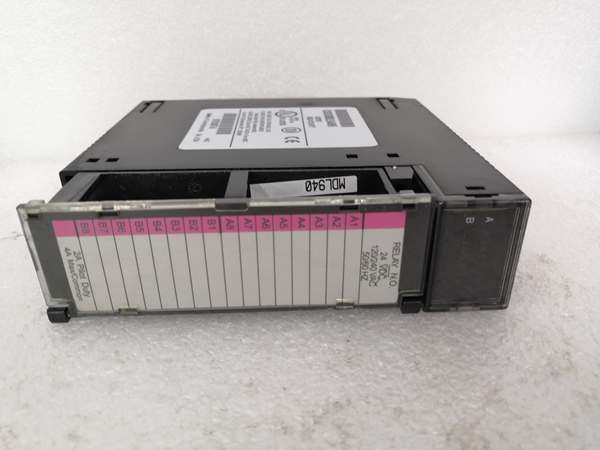
- Terminal Type: Removable terminal block with per-point common terminals
- Hot Swap: Supported on RX3i universal backplanes (IC695CHS series)
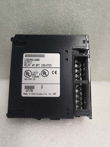
- Certifications: UL 508, CSA C22.2 No. 142, Class I Div 2 (Groups A, B, C, D)
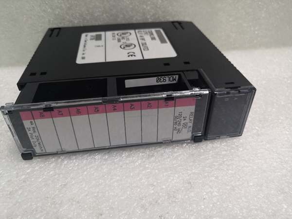
GE IC693MDL930
The Real-World Problem It Solves
When you’re pulling signals from 240V AC field devices—motor starters, auxiliary contacts, heavy-duty limit switches—you need an input module that can take a beating from line voltage transients without frying the backplane. The IC694MDL231 gives you per-point isolation, meaning each of the 8 inputs is electrically isolated from every other point and from the PLC logic. Wire up 8 different 240V AC circuits from 8 different panels, and a ground loop or voltage spike on one won’t take down the rest.
Where you’ll typically find it:
- Motor control center (MCC) interface panels where auxiliary contacts from starters and breakers feed back at 240V AC
- Heavy industry (steel mills, paper plants, mining) where 240V AC is the standard control voltage and electrical noise is brutal
- Legacy control system retrofits where field devices are already wired for 240V AC and changing to 24V DC isn’t practical
Bottom line: Bridges high-voltage AC field signals to the PLC with channel-level isolation—no shared commons, no cross-talk, no single-point-of-failure.
Hardware Architecture & Under-the-Hood Logic
The IC694MDL231 is an 8-channel AC input module with individual optical isolation on each point. Unlike grouped-input modules that share a common, each of the 8 inputs on this module has its own dedicated common terminal and its own isolation barrier. This means you can wire each input to a completely different AC power source without creating ground loops.
Signal Flow & Internal Architecture:
- Field Wiring Terminals: 8 input terminals plus 8 individual common terminals. Each input is a two-wire connection (hot + common). No shared commons exist internally.
- Input Filter Network: Each channel has a reactive RC filter (resistor-capacitor network) that provides noise filtering and determines the 30ms ON / 45ms OFF response time. This filter rejects high-frequency noise and contact bounce but introduces a deliberate delay.
- Optical Isolator Stage: After the RC filter, the AC signal drives an optocoupler (LED + phototransistor). This is the isolation barrier—250V AC continuous rating between field side and logic side. The optocoupler converts the AC signal to a logic-level DC signal.
- Logic-Level Processing: The isolated DC signal is then sampled by the module’s internal logic and mapped to the input status table (%I addresses). When 6mA or more flows through the input circuit, the corresponding bit in %I memory is set to 1.
- LED Status Indicators: Eight green LEDs on the module front panel are driven directly by the logic-level signals. LED ON = input point detecting voltage above the ON threshold.
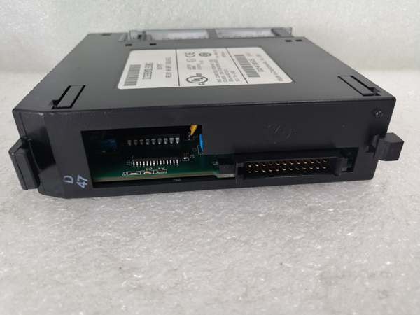
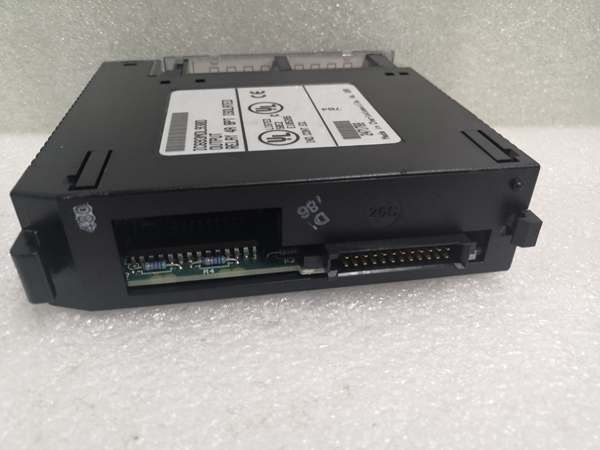
- Backplane Interface: The module communicates with the RX3i CPU via the backplane bus. The 60mA @ 5V DC power draw is from the backplane supply, not from the field wiring.
GE IC693MDL930
Field Service Pitfalls: What Rookies Get Wrong
Assuming All Inputs Share a Common
Most 24V DC input modules have a shared common, and rookies wire the IC694MDL231 the same way—tying all the common terminals together. This defeats the purpose of the isolated design. If you share a common, a voltage spike on one circuit can propagate to others through that common connection.
- Field Rule: Treat each input as a completely independent 2-wire circuit. Wire the hot to the input terminal and the neutral to the dedicated common for that specific point. If you’re using multiple AC sources, each source’s neutral goes to its own common terminal.
Applying DC Voltage to an AC-Only Input
The IC694MDL231 is designed for AC signals only. The reactive RC filter and optocoupler circuit require AC to function correctly. Applying 24V DC or 120V DC won’t work reliably—the input may never register, or may latch ON permanently.
- Quick Fix: If you need DC input capability, use the IC694MDL645 (24V DC) or IC694MDL634 (24V DC positive/negative logic) instead. Don’t force DC into an AC-rated module.
Ignoring the Response Time for Fast Signals
The 30ms ON / 45ms OFF response time is slow compared to 24V DC modules (often 1-10ms). This is a deliberate trade-off for noise immunity. If you’re trying to catch a 50ms pulse from a high-speed counter or encoder, this module will miss it.
- Field Rule: Use this module for relatively slow discrete signals—pushbuttons, selector switches, auxiliary contacts, relay outputs. For high-speed counting or pulse detection, use a high-speed counter module (IC694APU300) or a fast-response DC input module.
Not Accounting for Off-State Leakage Current
Some solid-state devices (SSRs, proximity switches) leak a small current when OFF. If the leakage exceeds 2.2mA, the IC694MDL231 may never see a true OFF state—the input will flicker or stay latched ON.
- Quick Fix: For devices with significant off-state leakage, add a bleeder resistor across the input terminals to divert leakage current below the 2.2mA threshold. Calculate resistor value based on your AC voltage and leakage current.
Wiring Multiple Phases to the Same Module
Because each input is isolated, you can theoretically wire different phases of 3-phase power to different inputs. However, if a fault occurs and phase-to-phase voltage appears between two commons, you’ve now got 415V AC (for 240V phase-to-neutral systems) across isolation barriers not rated for that voltage.
- Field Rule: Keep all inputs on the same module sourced from the same phase or the same AC circuit. If you need to monitor multiple phases, use separate modules or install additional isolation (interposing relays).
Commercial Availability & Pricing Note
Please note: The listed price is for reference only and is not binding. Final pricing and terms are subject to negotiation based on current market conditions and availability.


