
Description
Hard-Numbers: Technical Specifications
- Input Channels: 4 differential, individually configurable
- Output Channels: 2 single-ended, individually configurable
- Input Ranges: 0 to +10 V, -10 to +10 V, 0-20 mA, 4-20 mA, 4-20 mA Enhanced (negative counts for open-wire detection)
- Output Ranges: 0 to +10 V, -10 to +10 V, 0-20 mA, 4-20 mA
- Resolution: 12 bits (all ranges)
- Update Rate: 3 ms (all inputs); 2 ms per channel (outputs)
- Input Impedance: 250 Ω (current mode), 800 KΩ (voltage mode)
- Common Mode Rejection: >70 dB at DC and 60 Hz
- Output Load (Current Mode): 0-850 Ω @ 20V supply; up to 1350 Ω @ 30V supply
- Output Load (Voltage Mode): 5 mA max, 2 KΩ minimum resistance
- Isolation Rating: 250 VAC continuous / 1500 VAC for 1 minute (field-to-backplane, optical)
- Power Consumption: 95 mA from +5 VDC backplane; 150 mA from external +24 VDC supply
- External Supply Range: 20-30 VDC (ripple max 10%)
- Hot-Swap Support: Yes (RX3i universal backplane only)
- Operating Temperature: 0°C to +60°C (32°F to 140°F)

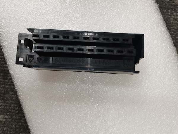
GE IC694ALG392
The Real-World Problem It Solves
When you’ve got a small process loop—say, a temperature transmitter, a pressure sensor, a flow meter, and a level probe feeding into two control valves—you don’t want to burn four slots on separate input and output cards. This module puts four differential inputs and two single-ended outputs in one slot. The inputs handle current or voltage. The outputs drive current or voltage. You configure each channel independently in Proficy Machine Edition.
Where you’ll typically find it:
- Skid-mounted process units where panel space is tight and I/O count is low
- Local PID loops on heat exchangers, dosing pumps, or filter presses
- Retrofit jobs where adding a second I/O rack isn’t an option
Bottom line: One slot, six channels, full flexibility. That’s the value proposition when you’re counting every inch of cabinet real estate.
Hardware Architecture & Under-the-Hood Logic
The IC694ALG442 combines an A/D converter for four input channels and a D/A converter for two output channels on a single board. The inputs are differential—each channel has its own + and – terminal, which rejects common-mode noise. The outputs are single-ended, meaning they share a common return. All signal conditioning happens on-board; the CPU just sees scaled 16-bit integer values.
Signal flow, step-by-step:
- Input Acquisition: Each differential input passes through an input filter (29-38 Hz cutoff) and an A/D converter. The filter rolls off high-frequency noise before conversion.
- Range Scaling: The module scales raw ADC counts to the configured range (e.g., 0 = 4 mA, 32000 = 20 mA). For 4-20 mA Enhanced mode, counts from -8000 to 0 map to 0-4 mA, enabling open-wire detection below 4 mA.
- Alarm Monitoring: High and low alarm limits are set per input channel in the configuration. When an input exceeds these limits, the module sets status bits that the CPU can read.
- Output Processing: The CPU writes a 16-bit count value to each output channel’s %AQ reference. The D/A converter maps this to the configured output range.
- Fault-State Behavior: If the CPU goes to Stop mode or external power is lost, the outputs can either Hold Last State or go to Downscale (0 mA / 0 V). This is configured per channel.
- Ramp Mode: Via COMMREQ commands, the outputs can be set to ramp to a new value over a specified time period instead of stepping instantly—useful for avoiding valve slam or process shock.
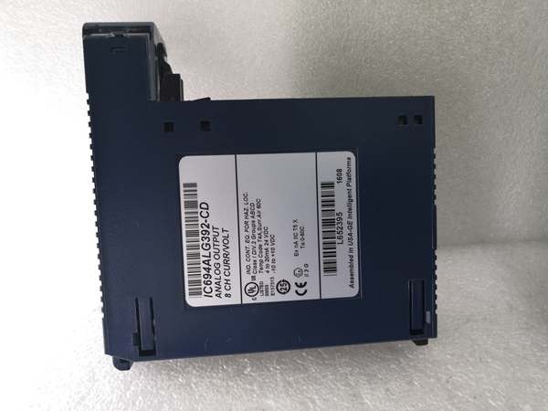
GE IC694ALG392
Field Service Pitfalls: What Rookies Get Wrong
Forgetting the External +24 VDC Supply
The module draws 95 mA from the backplane’s +5 VDC rail, but that only powers the module’s logic and LEDs. The analog output drivers need an external +24 VDC source. If the USER LED is off, your outputs will be dead even if the module is configured and the OK LED is on.
- Field Rule: Verify +24 VDC at the TB1 connector (universal backplane) or at the module’s terminal block (expansion backplane) before commissioning. Measure it under load—not just open-circuit.
Misunderstanding Differential Inputs
The four input channels are differential, not single-ended. Each channel has a + and – terminal. If you tie all the – terminals to a common ground and run single-ended wiring, you defeat the common-mode rejection and pick up ground-loop noise. This shows up as drifting readings or intermittent alarms.
- Quick Fix: For true differential wiring, run a twisted pair from each transmitter all the way to the module’s input terminals. Don’t share the – leg between channels unless you’re intentionally using a common return and understand the tradeoffs.
Open-Wire Detection Only Works in Enhanced Mode
Standard 4-20 mA input mode doesn’t detect open loops below 4 mA—the module just clips at 0 counts. If you need to know when a transmitter fails or a wire breaks, you must configure the input for “4-20 mA Enhanced” mode. This extends the range down to 0 mA and reports negative counts (-8000 to 0) for currents below 4 mA.
- Field Rule: For any safety-critical 4-20 mA input, use Enhanced mode and alarm on negative counts. This catches open loops, failed transmitters, and reversed wiring.
Commercial Availability & Pricing Note
Please note: The listed price is for reference only and is not binding. Final pricing and terms are subject to negotiation based on current market conditions and availability.


