
Description
Hard-Numbers: Technical Specifications
- Input Voltage: 24 VDC nominal
- Input Voltage Range: 8-30 VDC (startup), 2-30 VDC (operating)
- Total Output Capacity: 30W maximum
- +5VDC Output: 5.0-5.2VDC (5.1VDC nominal), 30W max (6A @ 5VDC)
- +24VDC Relay Output: 24-28VDC, 5W max
- +24VDC Isolated Output: 21.5-28VDC, 20W max
- +5VDC Backplane Current: Approximately 6A maximum (double PWR321 capacity)
- Input Power: 50W DC at full load
- Inrush Current: 4A peak, 250ms maximum
- Holdup Time: 0 ms minimum (no bulk capacitor for holdup – tradeoff for DC input optimization)
- Overvoltage Protection: 6.4-7VDC on +5V rail
- Overcurrent Protection: 7A maximum on +5V rail
- Operating Temperature: 0-60°C
- Temperature Derating: Above 50°C, +5VDC current derates to 4.0A maximum at 60°C
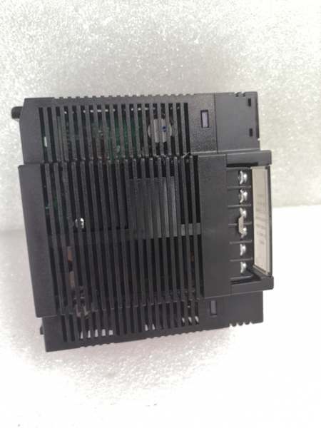
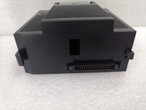
- Mounting Location: Leftmost slot of baseplate only
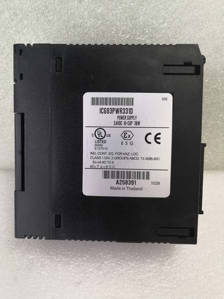
- Internal Fuse: GE catalog 44A724627-109 (field-replaceable)
- Certifications: CE compliant, cULus listed, Class I Division 2 rated
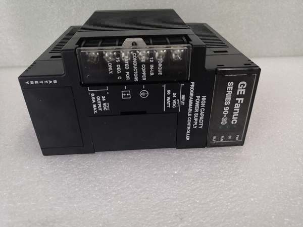
GE IC693PWR331
The Real-World Problem It Solves
The PWR331 exists for one specific reason: DC-powered systems with heavy +5VDC loads. Unlike PWR321’s AC/DC flexibility, PWR331 is purpose-built for 24VDC applications, and its killer feature is the 30W +5VDC output—double the capacity of PWR321. This makes it the go-to choice for mobile equipment (mining trucks, construction machinery), battery-backed installations, and solar-powered PLC systems where every watt of +5VDC capacity matters.
The PWR331 advantage in three scenarios:
- Mobile Equipment with Battery Power: Mining haul trucks and port cranes run 24VDC battery systems that fluctuate between 18-30VDC. PWR331’s wide 2-30VDC operating range handles battery sag and alternator spikes without additional regulation. The 30W +5VDC output powers dense I/O arrays for vehicle monitoring systems—sensors, pressure transducers, limit switches—where PWR321 would hit its 15W ceiling and require a second power module.
- High-Density I/O Racks: Control systems with 12+ high-power I/O modules (digital inputs, analog input modules, high-speed counters) need serious +5VDC current. PWR331 delivers 6A on the +5VDC rail, supporting configurations that would require two PWR321 modules running in parallel. The result: one module instead of two, reduced cabinet space, fewer failure points, lower heat load.
- Solar-Powered Remote Installations: Off-grid solar arrays provide 24VDC power to PLC systems at remote pumping stations, communication repeaters, or environmental monitoring sites. PWR331’s DC-only design eliminates the AC rectification stage, improving efficiency in solar applications where every watt counts. The wide input range accommodates battery voltage swings (22-28VDC typical) without external DC-DC converters.
Bottom line: is the +5VDC workhorse of the 90-30 lineup. When your application is 24VDC-powered and you need max +5VDC current, delivers double the capacity of PWR321 in a single package. If you’re running AC power or don’t need the extra +5VDC capacity, stick with or the compact PWR330J.
Hardware Architecture & Under-the-Hood Logic
The shares the same basic three-output architecture as (regulated +5VDC, relay 24VDC, isolated 24VDC), but with a critical difference: the +5VDC output stage is designed for double the current capacity. The architecture tradeoff is the elimination of the bulk holdup capacitor— has 0ms holdup time, unlike ‘s 20ms holdup—since DC-powered systems typically have battery backup that eliminates the need for AC-loss holdup capability.
| Feature | (DC-Only) | (AC/DC) |
|---|---|---|
| Input Type | 24VDC only | 120/240VAC or 125VDC |
| Input Range | 2-30VDC operating | 85-264VAC / 100-300VDC |
| +5VDC Capacity | 30W (6A) | 15W (3A) |
| Holdup Time | 0ms | 20ms |
| Bulk Capacitor | None (optimized for DC input) | Present (for AC dropout) |
| Primary Application | DC-powered systems, high +5VDC loads | General-purpose AC/DC systems |
Internal signal flow and protection logic:
- Input stage: 24VDC enters through EMI filter and reverse polarity protection diode—critical for mobile applications where battery cables can be accidentally reversed. No bridge rectifier needed (DC-only design), reducing losses. The wide 2-30VDC range is handled by a buck-boost pre-regulator that stabilizes input voltage before the main switching stage.
- Primary switching: High-frequency DC-DC converter optimized for DC input (no line frequency rectification required). The +5VDC output stage uses doubled copper trace width and reinforced PCB pours to handle 6A current with minimal voltage drop. Power semiconductors are sized for continuous 30W output at elevated temperatures—critical for mobile equipment where under-hood temperatures can exceed 60°C.
- Output isolation: Three separate secondary windings provide isolated rails. The +5VDC rail uses heavy-duty rectifier diodes and low-ESR output capacitors to maintain stable voltage under 6A load. The dual 24VDC outputs retain the same isolation topology as —relay output shares logic ground, isolated output floats independently.
- Protection circuitry: Current limiters on each rail with faster response time for the high-current +5VDC rail (10µs) to prevent damage during transient overloads. Overcurrent threshold set to 7A on +5V rail—allows brief surge currents while protecting against sustained overload. Reverse polarity protection at input prevents catastrophic damage from miswired battery connections.
- Diagnostic monitoring: Voltage dividers feed into supervisory circuit driving front-panel LEDs (PWR, OK, FAULT). The +5VDC voltage monitoring is tighter tolerance due to the higher current—±1% vs ±2% on —to detect voltage sag earlier in high-load applications.
GE IC693PWR331
Field Service Pitfalls: What Rookies Get Wrong
Input Voltage Expectations – The “12VDC” MistakeTechs see “24VDC” on the label and assume can handle standard 12VDC vehicle systems. It can’t. The operating range is 2-30VDC, but the startup requirement is 8VDC minimum. won’t power up from a discharged 12V battery (10-11V), and techs replace the module unnecessarily when the real problem is a weak battery or undersized supply.
Field Rule: Verify input voltage is ≥8VDC at startup and ≥2VDC during operation. If you’re powering from a 12VDC vehicle system, ensure the battery is fully charged or use a DC-DC boost converter. Don’t blame for a 10VDC input that fails to start—it’s working as designed.
Holdup Time ConfusionTechs accustomed to ‘s 20ms holdup time expect to ride through momentary power interruptions. It won’t. has 0ms holdup—DC input drops, output drops instantly. This causes PLC brownouts in mobile equipment with loose battery connections or poorly maintained DC bus bars.
Quick Fix: If your application requires holdup time, add external capacitance to the 24VDC bus or ensure battery backup is properly maintained. assumes your DC source is stable—if it’s not, add external holdup. Don’t expect the module to bridge 100ms interruptions like does on AC systems.
+5VDC Overload MisdiagnosisWith 6A capacity on the +5VDC rail, techs assume is “unlimited” and pack racks with excessive I/O modules. The module trips overcurrent protection or overheats, and techs blame “weak design” when the real issue is exceeding the 30W total capacity. The +5VDC may deliver 6A, but total output (all rails combined) is still limited to 30W.
Field Rule: Calculate total load across all three rails, not just +5VDC. If you’re drawing 25W on +5VDC, you only have 5W left for the 24VDC outputs. Don’t max out +5VDC and expect full 24VDC capacity simultaneously—total power is the limit.
Temperature Derating in High-Ambient ApplicationsTechs install in mobile equipment engine compartments where ambient temperatures reach 55-60°C. At 60°C, the +5VDC current derates to 4.0A—33% reduction from room temperature. Techs expect full 6A output and experience undervoltage faults when the module thermally protects itself.
Quick Fix: Check the temperature derating curve before installation in high-ambient environments. At 55°C+, plan for reduced +5VDC capacity (4.0A max at 60°C). If you need full 6A, add cooling or relocate the module to a cooler compartment. Don’t assume 30W is available at 60°C—it’s not.
Reverse Polarity Protection Limits has reverse polarity protection, but techs test it with car batteries in reverse—protection diode conducts, blows internal fuse (44A724627-109), and techs assume the module is dead. The protection works, but the fuse sacrifices itself. Techs replace the entire module when they should just swap the fuse.
Field Rule: If fails to power up after reverse polarity incident, check the internal fuse first. Remove the module, locate fuse holder, test continuity across 44A724627-109. If open, replace with GE catalog fuse—don’t scrap the module. The reverse polarity protection did its job by blowing the fuse.
Battery Charging Voltage OvershootSolar-powered systems with MPPT charge controllers can see voltage spikes to 30-32VDC during battery equalization. ‘s maximum input is 30VDC—extended exposure to 32VDC causes overvoltage stress on input capacitors. Techs see premature capacitor failures and blame “defective modules” when the real issue is charge controller voltage setpoint.
Quick Fix: Verify your solar charge controller’s maximum output voltage. If it exceeds 30VDC, add a voltage limiter or adjust the charge controller setpoint. handles momentary spikes but continuous overvoltage degrades input stage components. Monitor input voltage with a logger if you suspect overshoot.
Fuse Replacement with Wrong Ratings uses the same fuse catalog number as (44A724627-109), but techs substitute generic 5A automotive fuses “because they fit.” The GE fuse is a time-delay 5A fuse designed for the inrush characteristics of the DC-DC converter. Generic fuses blow during normal startup, causing nuisance trips and “unreliable” complaints.
Field Rule: Always use GE catalog 44A724627-109 for fuse replacement. The time-delay characteristic is critical for 4A peak inrush current over 250ms. Don’t substitute with fast-acting or automotive fuses—if the fuse blows repeatedly during startup, check your wiring, not the fuse rating.
Commercial Availability & Pricing Note
Please note: The listed price is for reference only and is not binding. Final pricing and terms are subject to negotiation based on current market conditions and availability.


