
Description
Hard-Numbers: Technical Specifications
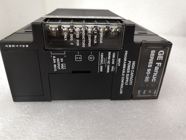
- Input Voltage: 120/240 VAC or 125 VDC nominal
- AC Input Range: 85-264 VAC (50/60Hz)
- DC Input Range: 100-300 VDC
- Total Output Capacity: 30W maximum
- +5VDC Output: 5.0-5.2VDC (5.1VDC nominal), 15W max
- +24VDC Relay Output: 24-28VDC, 15W max
- +24VDC Isolated Output: 21.5-28VDC, 20W max
- +5VDC Backplane Current: Approximately 3A maximum
- Input Power: 90VA (AC) / 50W (DC) at full load
- Inrush Current: 4A peak, 250ms maximum
- Holdup Time: 20ms minimum
- Overvoltage Protection: 6.4-7VDC on +5V rail
- Overcurrent Protection: 4A maximum on +5V rail
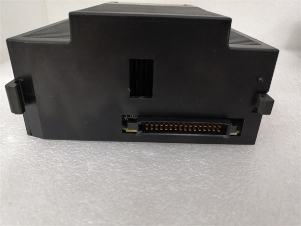
- Communication: RS-485 serial port (9-pin sub-D connector)
- Operating Temperature: 0-60°C
- Mounting Location: Leftmost slot of baseplate only
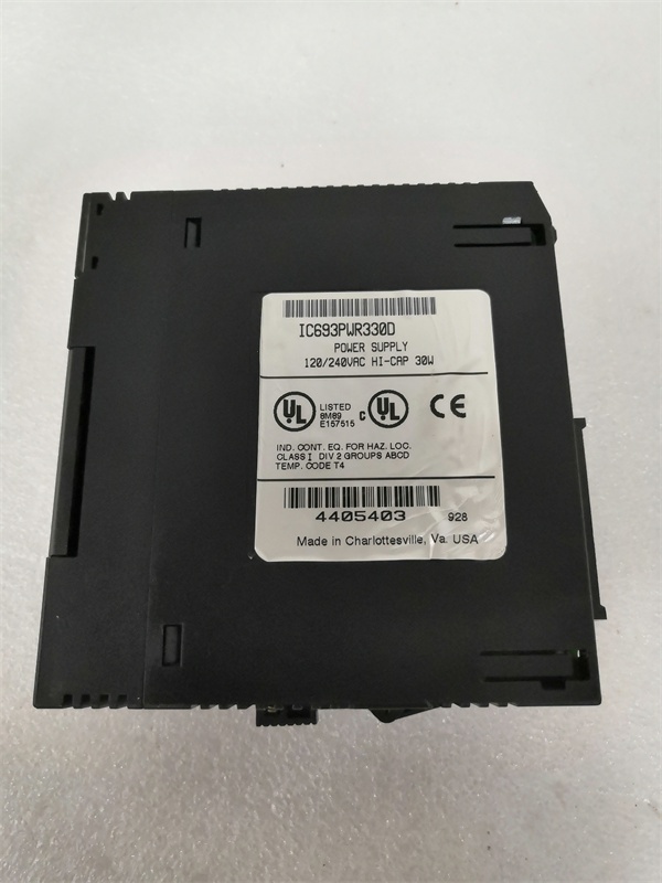
- Internal Fuse: GE catalog 44A724627-109 (field-replaceable)
- Certifications: CE compliant, cULus listed, Class I Division 2 rated
- Physical Size: Reduced height/depth vs standard PWR321 (compact form factor)
GE IC693PWR330
The Real-World Problem It Solves
The PWR330B solves the same cabinet space crunch as base PWR330—delivering full 30W PWR321 functionality in physically smaller package. Revision B includes component-level refinements that improve reliability in the compact form factor: upgraded capacitors with higher temperature ratings, reinforced PCB traces for the +5VDC high-current path, and improved thermal management in the tighter space envelope. These aren’t listed in standard spec sheets, but in the field they translate to fewer heat-related failures in confined machine consoles.
Where you’ll typically find it:
- CNC machine control panels where space behind the backplane is limited by moving axes
- Packaging machine PLC retrofits fitting into existing enclosures without cabinet modifications
- Mobile equipment consoles (forklift AGVs, agricultural sprayers) where every cubic inch matters
Bottom line: PWR330B delivers same 30W punch as PWR321 but fits where standard supplies don’t, with Revision B’s component upgrades making it more resilient in tight, hot spaces.
Hardware Architecture & Under-the-Hood Logic
The PWR330B shares identical electrical architecture to PWR321 and base PWR330—AC/DC input, EMI filtering, bridge rectification, high-frequency switching, three isolated output rails. The Revision B updates focus on thermal management and current path reinforcement in the compact form factor: heavier copper pours on the PCB for the +5VDC output traces (reducing resistance and voltage drop despite tighter routing), upgraded electrolytic capacitors with 105°C ratings (critical in reduced-ventilation environments), and optimized heatsink coupling to handle 30W thermal load in reduced volume.
Internal signal flow and protection logic:
- Input stage: AC/DC enters through EMI filter and bridge rectifier, feeding bulk capacitor for 20ms holdup time. Component layout is tighter than PWR321, but Revision B uses higher-temperature-rated components for reliability in confined spaces.
- Primary switching: High-frequency DC-DC converter generates intermediate bus voltage. Revision B may include updated switching transistors with lower thermal resistance to handle 30W in compact envelope—efficiency remains 85% typical, but thermal management is improved.
- Output isolation: Three separate secondary windings create isolated rails with same current capability as PWR321. Revision B uses reinforced PCB copper pours to minimize voltage drop on +5VDC rail despite tighter component spacing.
- Protection circuitry: Current limiters on each rail sense output current—when you hit 110% of rated load, PWM throttles back. If short circuit occurs, protection crowbar fires, shutting down that rail instantly while leaving other rails alive.
- Diagnostic monitoring: Voltage dividers feed into supervisory circuit that drives front-panel LEDs and RS-485 status registers. Revision B threshold tuning matches behavior—no electrical differences in diagnostic response compared to base PWR330.
GE IC693PWR330
Field Service Pitfalls: What Rookies Get Wrong
Terminal Block Count ConfusionPWR330B uses 5-terminal blocks vs 6-terminal blocks on later revisions. Techs swap a PWR321W/U/Y for PWR330B without realizing the terminal arrangement is different. Fewer screws mean fewer connection points—if you’re retrofitting from a later revision, your existing wiring might need consolidation.
Field Rule: Compare terminal block screw count before removing the old module. PWR330B will have 5 screws—verify your existing wiring diagram maps to the reduced block layout. The terminal block is removable—swap it if you’re retrofitting and want to preserve wire connections, but prepare for possible wire consolidation if you’re coming from a 6-terminal .
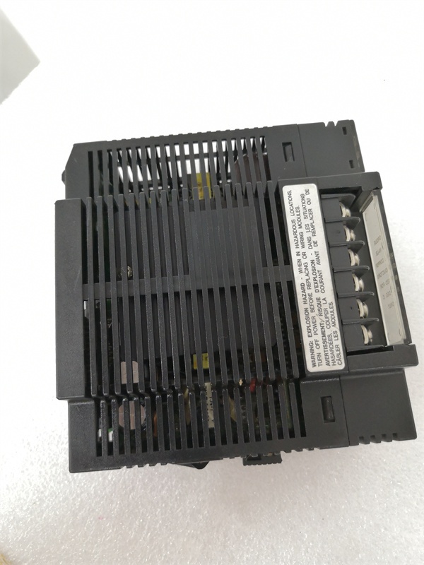
Thermal Derating in Confined SpacesRevision B includes improved thermal management, but that doesn’t eliminate thermal stress in tight compartments. Techs jam into sealed machine consoles with zero airflow and expect it to handle 30W continuously like a in a ventilated cabinet. The compact form factor reduces convection paths—thermal management becomes more critical, not less.
Quick Fix: Calculate clearance around before installation. You need at least 25mm (1 inch) of clearance above and below for convection cooling. If you’re installing in a tight machine console, add forced ventilation or derate your load. Don’t assume Revision B’s thermal improvements make it immune to confined-space overheating.
Fuse Rating Verification uses the same internal fuse catalog number as (GE 44A724627-109), but techs get confused by the compact layout and struggle to locate the fuse holder. The fuse is there, but access might be tighter due to reduced component spacing in the Revision B design.
Field Rule: Remove the module from the baseplate for fuse replacement—don’t try to access the fuse in situ if clearance is tight. The compact design means less working room around the fuse holder. Work on a bench where you can see clearly, and verify the fuse catalog number printed on the fuse end cap matches GE 44A724627-109.
Voltage Drop on +5VDC RailRevision B’s reinforced PCB traces reduce but don’t eliminate voltage drop under full 3A load. Techs swap standard for expecting to fix “voltage sag” complaints in densely packed racks. The +5VDC still drops 0.2-0.3V under full load—that’s normal, not a supply defect. The improvements help, but can’t fix undersized backplane wiring or corroded terminals.
Quick Fix: Measure voltage at the supply terminals first. If you see 5.1VDC at the supply but 4.7VDC at the far end of the backplane, your problem is wiring or terminal resistance, not the supply. Revision B helps, but it can’t fix undersized conductors or corroded connections. Check your backplane wiring gauge and terminal condition before blaming the module.
Connector Clearance in Tight Installations‘s compact design positions the RS-485 serial connector closer to adjacent modules or cabinet edges. Techs install and realize they can’t plug in programming cables without removing neighboring modules. The connector exists, but physical access is tighter due to reduced form factor.
Field Rule: Check connector clearance before final installation. Verify you can plug in your RS-485 cables without hitting adjacent modules or cabinet structures. If access is tight, leave one empty slot next to or reroute your cables. Don’t discover access problems after the cabinet is buttoned up and the machine is assembled.
Heat Sink Obstruction in Machine ConsolesRevision B’s optimized heatsink design relies on convection airflow. Techs install directly behind cabinet doors or in sealed compartments, obstructing convection paths entirely. The heatsink needs free air movement—block it completely and the supply will overheat despite Revision B’s thermal improvements.
Quick Fix: Maintain at least 25mm clearance above the heatsink fins. If you’re installing in a sealed machine console, add ventilation slots or cutouts aligned with the heatsink area. Don’t block airflow with cable bundles, door seals, or other modules. The compact design relies on proper airflow more than larger supplies—obstruct it and thermal problems will surface quickly.
Revision Mixing in RetrofitsTechs replace a failed (standard form factor) with (compact form factor) without verifying physical clearance. fits the backplane slot, but adjacent cabinet structures, door frames, or cable trays might not clear the compact dimensions. The module installs electrically but mechanically interferes with other components.
Field Rule: Verify physical clearance around the leftmost slot before installing . Measure depth from backplane to nearest obstruction (door, cable tray, structural member). might be shorter in depth than , but ensure nothing behind the backplane interferes with the module’s rear connector or heatsink area. Don’t assume compact always fits—it might clear the slot but hit other components.
Load Misunderstanding on “Compact” DesignTechs assume ‘s compact size means reduced current capacity, then load it conservatively “to be safe” when the module can actually handle full 30W. Electrically, it’s identical to —same 30W total capacity, same 3A +5VDC limit. The compact form factor is physical only, not electrical derating.
Quick Fix: Treat exactly like for load calculations. Don’t derate it just because it’s smaller—the electrical ratings are identical. If your installation handled 25W comfortably, will handle the same load. Calculate your load using specs—same numbers apply.
Commercial Availability & Pricing Note
Please note: The listed price is for reference only and is not binding. Final pricing and terms are subject to negotiation based on current market conditions and availability.


