
Description
Hard-Numbers: Technical Specifications
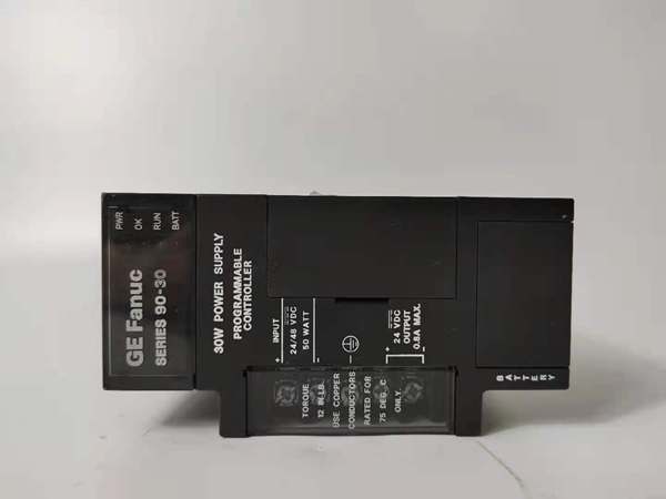
- Input Voltage: 120/240 VAC or 125 VDC nominal
- AC Input Range: 85-264 VAC (50/60Hz)
- DC Input Range: 100-300 VDC
- Total Output Capacity: 100W maximum (same as PWR322)
- +5VDC Output: 5.0-5.2VDC (5.1VDC nominal), 40W max
- +24VDC Relay Output: 24-28VDC, 30W max
- +24VDC Isolated Output: 21.5-28VDC, 40W max
- +5VDC Backplane Current: Approximately 8A maximum
- Standard Holdup Time: 20ms minimum (internal capacitor bank)
- Extended Holdup Time: Up to 10 seconds with optional external battery backup module
- Input Power: 120VA (AC) / 70W (DC) at full load
- Inrush Current: 10A peak, 250ms maximum
- Overvoltage Protection: 6.4-7VDC on +5V rail
- Overcurrent Protection: 8A maximum on +5V rail
- Communication: RS-485 serial port (9-pin sub-D connector)
- Battery Backup Interface: Supports connection to external battery backup module (IC693ACC300 series or equivalent)
- Operating Temperature: 0-60°C
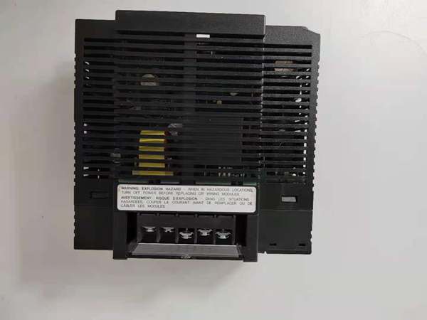
- Mounting Location: Leftmost slot of baseplate only
- Internal Fuse: GE catalog 44A724627-109 or revision-specific equivalent
- Certifications: CE compliant, cULus listed, Class I Division 2 rated
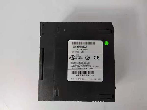
GE IC693PWR322
The Real-World Problem It Solves
The PWR324R solves the momentary power interruption problem in facilities where grid sags or brief brownouts (under 1 second) cause PLC shutdowns that 终止 production lines. Standard power supplies have 20ms holdup—enough to ride through brief voltage dips but not through intentional grid switching, motor starting sags, or utility reclosing events. The PWR324R’s extended holdup capability (up to 10 seconds with external battery) keeps your rack alive through these events without triggering alarms or requiring cold restarts.
Where you’ll typically find it:
- Chemical process plants where utility reclosing cycles cause 2-5 second interruptions
- Steel mill E-trip systems requiring continuous operation during power quality events
- Semiconductor fabs where voltage sags from large motor starts can’t be tolerated
Bottom line: PWR324R is standard PWR322 100W capacity with ride-through insurance—same power delivery, but your rack stays powered when the grid hiccups for a few seconds.
Hardware Architecture & Under-the-Hood Logic
The PWR324R shares identical power train architecture to PWR322—AC/DC input, EMI filtering, bridge rectification, high-frequency switching at 100W capacity. The critical difference is in the holdup extension circuitry: larger input capacitor bank provides baseline 20ms holdup, and a dedicated battery charging/discharge circuit interfaces with external battery backup modules. When AC/DC input fails or drops below threshold, the backup circuit seamlessly switches to external battery power, maintaining +5VDC output without interruption. The transition is automatic and transparent to the PLC—you’ll see the input voltage fault LED, but your rack keeps running.
Internal signal flow and protection logic:
- Input stage: Same beefy EMI filter and bridge rectifier as PWR322, but with larger bulk capacitor bank for extended baseline holdup (typically 40-50ms vs 20ms on standard supplies).
- Primary switching: Same high-power DC-DC converter architecture. The switching stage continues running seamlessly whether input is AC/DC or battery power—no switchover gap.
- Battery backup interface: Dedicated charging circuit maintains external battery at float voltage when AC/DC is present. When input voltage fails, transfer circuit disconnects input source and switches to battery power within milliseconds.
- Output isolation: Three separate secondary windings with same current capability as PWR322. Output regulation remains stable during switchover to battery power—no voltage sag or transient.
- Protection circuitry: Same scaled current limiters as PWR322 (8A for +5VDC). Additional battery protection circuit prevents over-discharge of external battery and isolates battery during faults.
- Diagnostic monitoring: Enhanced supervisory circuit monitors both input voltage and battery status via RS-485 registers. You can read battery voltage, charge state, and backup time remaining through HMI or SCADA.
GE IC693PWR322
Field Service Pitfalls: What Rookies Get Wrong
Battery Selection MismatchTechs connect automotive lead-acid batteries or wrong-capacity units to the PWR324R backup interface. The charging circuit is designed for specific battery chemistries (typically sealed lead-acid or Ni-Cd)—wrong batteries won’t charge properly or can damage the module. I’ve seen techs fry the charging circuit by connecting flooded lead-acid batteries that outgas hydrogen.
Field Rule: Use only GE-approved battery backup modules (IC693ACC300 series or equivalent). If you’re sourcing aftermarket batteries, match the chemistry and voltage rating exactly to the GE spec. Never exceed the recommended Ah capacity—the charging circuit isn’t designed for larger banks and will overheat.
Holdup Time ExpectationsTechs expect PWR324R to provide full 10-second holdup with any battery. Reality: holdup time depends on load and battery capacity. If you’re pulling 80W continuous and using a small 7Ah battery, you’ll get 3-5 seconds, not 10. The 10-second figure is best-case at reduced load.
Quick Fix: Calculate actual holdup time: Battery Ah × Battery Voltage × 0.8 (discharge efficiency) ÷ Load Watts. For example, 7Ah × 24V × 0.8 ÷ 60W = 2.24 hours (theoretical), but in practice, you get about 2-3 minutes at full 100W load. Design your system for realistic holdup based on your actual load, not marketing numbers.
Fuse Rating Confusion with Battery Connected might use a different internal fuse rating than standard due to battery backup circuitry. Techs blindly install standard GE 44A724627-109 fuse and wonder why it blows when the battery engages during switchover. The inrush from battery connection can be higher than expected.
Field Rule: Consult the fuse catalog number printed on your specific revision’s internal fuse holder before replacement. The fuse rating accounts for both normal load and battery switchover transients. Don’t substitute with standard fuse—match the exact catalog number to avoid nuisance trips or inadequate protection.
Battery Disconnect During MaintenanceTechs disconnect the battery before powering down the for maintenance. When AC power returns, the charging circuit sees the battery missing and can fault or shut down. I’ve seen techs chase “power supply failure” for hours when the real issue was an unplugged battery.
Quick Fix: Always disconnect battery after removing AC/DC input power, and reconnect battery before reapplying AC/DC. The charging circuit expects the battery present during startup—if it’s missing, you’ll get fault LEDs and the supply might not initialize properly.
Ventilation Around Battery CompartmentIf you’re installing the battery backup module adjacent to in the same cabinet, techs forget that batteries generate heat during charging. 100W from the supply plus heat from battery charging can cook a poorly ventilated cabinet, especially if you’re running near full load.
Field Rule: Calculate total heat load—supply output losses plus battery charging losses (typically 10-15% of battery charge current). If your cabinet is already warm, add forced ventilation or relocate the battery compartment. Batteries degrade faster at elevated temperatures, reducing holdup time over time.
Diagnostic Misinterpretation During SwitchoverTechs see red input fault LED and assume supply failure, missing that the module switched to battery power and is operating normally. The LED indicates input source failure, not supply failure—the +5VDC output is still solid, and your rack is still running.
Quick Fix: Check all three LEDs—input fault LED on with OK LED solid means battery switchover occurred and supply is functioning correctly. Only troubleshoot if OK LED is off. Many nuisance maintenance calls result from techs misinterpreting normal switchover behavior as module failure.
Battery Aging and Holdup Time ReductionTechs install , verify 10-second holdup during commissioning, then ignore battery health for years. Batteries degrade over time, especially in high-temperature environments, and your holdup time drops from 10 seconds to 2-3 seconds without warning. When the real power sag hits, the rack dies because the battery can’t deliver.
Field Rule: Implement annual holdup time testing—disconnect AC/DC input and measure how long the rack stays powered. If holdup time drops below 50% of commissioned value, replace the battery. Don’t wait for the battery to fail completely during a real power event.
Commercial Availability & Pricing Note
Please note: The listed price is for reference only and is not binding. Final pricing and terms are subject to negotiation based on current market conditions and availability.


