
Description
System Architecture & Operational Principle
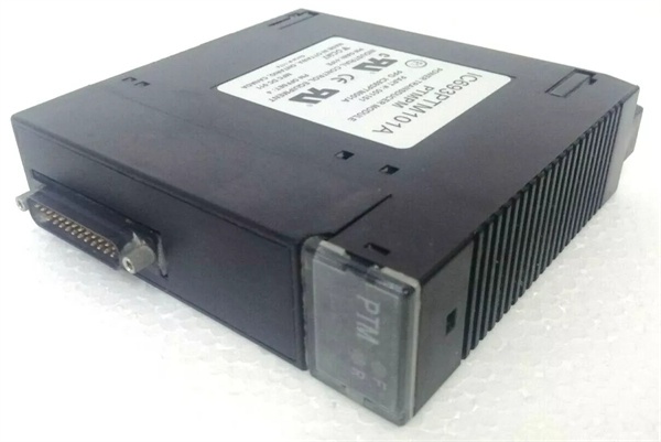
The IC693PTM101A is a power supply module designed specifically for the GE 90-30 PLC platform. It occupies a single slot in any baseplate (CPU baseplate, expansion baseplate, or remote baseplate) and provides regulated DC power for the entire PLC rack and external field devices. Unlike communication modules which are restricted to CPU baseplates, power supply modules can be installed in any 90-30 baseplate type, including CPU baseplates, expansion baseplates, and remote baseplates, providing flexibility for power distribution across distributed PLC architectures.
AC Input Voltage Conversion
The PTM101A accepts a wide range of AC input voltages: 120VAC or 240VAC at 50/60Hz. The input voltage is factory-configured via an internal jumper or switch that must be set before installation based on the facility’s available line voltage. Incorrect input voltage configuration will damage the module and potentially other PLC components. The module includes overvoltage and undervoltage protection circuits that shut down the power supply if input voltage exceeds approximately 264VAC (for 240VAC configuration) or falls below approximately 85VAC (for 120VAC configuration), protecting the connected modules from voltage spikes or sags.
Dual DC Output Rails
The power supply generates two independent DC output rails:
- 5VDC Rail: Primary backplane power rail that provides power to all modules installed in the baseplate. This includes CPUs, I/O modules, communication modules, coprocessors, and other specialized modules. The PTM101A can deliver up to 5A at 5VDC (25W) to the backplane, sufficient to support moderately loaded racks with multiple I/O modules and a mid-range CPU.
- 24VDC Rail: Secondary output rail designed primarily for powering external field devices such as sensors, proximity switches, limit switches, and small solenoids. The PTM101A can deliver up to 0.5A at 24VDC (12W) to field devices, reducing the need for separate external power supplies for low-power field devices.
The two output rails are galvanically isolated from each other and from the AC input, providing noise immunity and preventing ground loops when field devices are powered from the 24VDC rail. This isolation is particularly important in industrial environments where VFDs, motor starters, and welding equipment introduce significant electrical noise.
Current Limiting and Short-Circuit Protection
Both DC output rails incorporate independent current limiting and short-circuit protection circuits:
- 5VDC Rail Protection: If the backplane current draw exceeds approximately 5.5A (110% of rated capacity), the current limiter reduces output voltage to limit current to approximately 5.5A. If a short circuit occurs (output impedance approaches zero ohms), the protection circuit shuts down the 5VDC output completely to prevent damage to the power supply and backplane components.
- 24VDC Rail Protection: If the field device current draw exceeds approximately 0.6A (120% of rated capacity), the current limiter reduces output voltage to limit current. If a short circuit occurs on the 24VDC output, the protection circuit shuts down the 24VDC output while attempting to maintain the 5VDC backplane power.
The protection circuits are non-latching—once the overload or short circuit condition is removed, the power supply automatically restarts and resumes normal operation without requiring manual intervention.
Diagnostic LED Indicators
The PTM101A includes two LED indicators on the front panel for status monitoring:
- PWR LED: Illuminates when AC input voltage is present and within the acceptable operating range (approximately 85-264VAC depending on configuration). If the PWR LED is OFF, check AC input wiring, line voltage, and the internal fuse.
- OK LED: Illuminates when both DC output rails (5VDC and 24VDC) are within specification and no protection circuits are active. If the OK LED is OFF while the PWR LED is ON, check for overloaded output rails, short circuits, or output wiring faults.
The LED indicators provide immediate visual feedback during startup and troubleshooting, enabling rapid identification of power-related issues without requiring external test equipment.
Field-Replaceable Fuse
The PTM101A includes a field-replaceable fuse (typically 5x20mm glass fuse, 2A/250VAC for 120VAC configuration, 1A/250VAC for 240VAC configuration) that protects the module and the facility’s electrical system from catastrophic failures. The fuse holder is accessible from the front panel, allowing rapid fuse replacement without removing the module from the rack. Always disconnect AC input power and verify zero voltage at the input terminals before replacing the fuse. Replace only with the specified fuse type and rating—using incorrect fuse ratings can cause safety hazards and damage to the module.
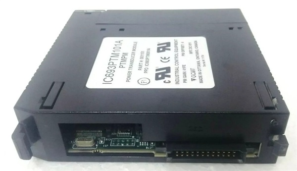
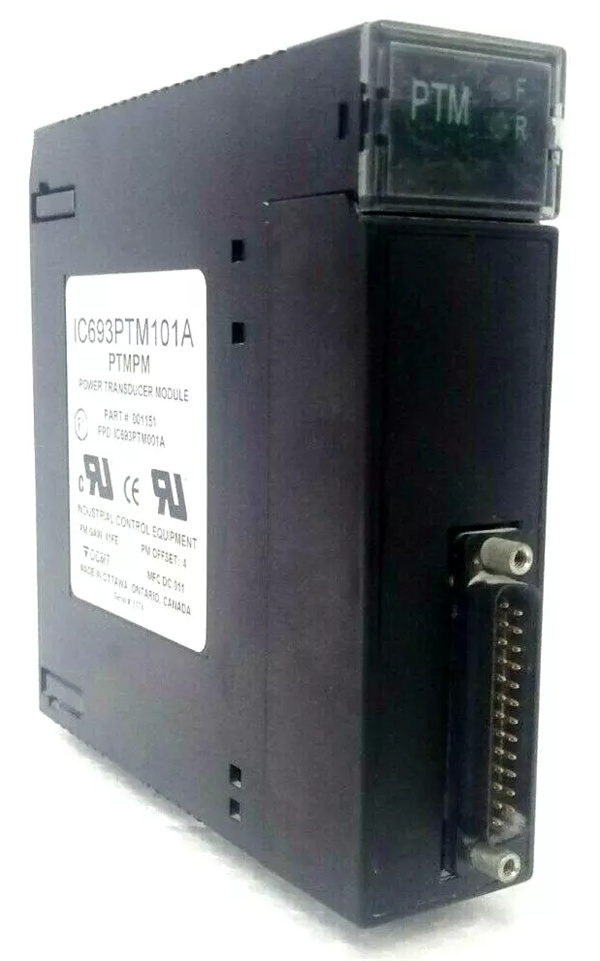
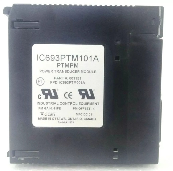
IC693PTM101A
Core Technical Specifications
- Input Voltage: 120VAC or 240VAC (factory-configurable via internal jumper)
- Input Frequency: 50/60Hz
- Input Voltage Range: 85-132VAC (120VAC configuration) / 170-264VAC (240VAC configuration)
- Input Current: 2.0A @ 120VAC / 1.0A @ 240VAC (typical)
- 5VDC Output: 5VDC @ 5A (25W) – Backplane power rail
- 24VDC Output: 24VDC @ 0.5A (12W) – Field device power rail
- Total Output Capacity: 30W (5VDC + 24VDC combined)
- Output Regulation: ±5% (load regulation), ±2% (line regulation)
- Overcurrent Protection: Current limiting at approximately 110% of rated output
- Short-Circuit Protection: Auto-recovery shutdown on output short circuits
- Overvoltage Protection: Shutdown if input voltage exceeds approximately 110% of configured range
- Undervoltage Protection: Shutdown if input voltage falls below approximately 70% of configured range
- LED Indicators: PWR (input power present), OK (outputs within specification)
- Fuse Protection: Field-replaceable 5x20mm fuse (2A/250VAC for 120VAC, 1A/250VAC for 240VAC)
- Mounting Location: Any slot in any baseplate (CPU, expansion, or remote baseplate)
- Backplane Current Draw: Provides up to 5A @ 5VDC to backplane
- Field Device Current: Provides up to 0.5A @ 24VDC to external devices
- Operating Temperature: 0°C to 60°C
- Storage Temperature: -40°C to 85°C
- Humidity: 5% to 95% non-condensing
- Altitude: Up to 2000m (derate above 2000m)
- Dimensions: 80mm x 114mm x 54mm (H x W x D)
- Weight: Approximately 0.3kg
- Documentation: GFK-0255 (Series 90-30 Power Supply Modules User’s Manual)
Customer Value & Operational Benefits
Universal AC Input Voltage Flexibility
The PTM101A’s ability to accept either 120VAC or 240VAC input via internal configuration provides global compatibility and reduces inventory requirements. Manufacturing facilities with multiple global sites can standardize on a single power supply model for all 90-30 PLC installations worldwide, reducing spare parts inventory and simplifying maintenance procedures. During facility upgrades or voltage standardization initiatives (e.g., converting from 120VAC to 240VAC for efficiency), the same power supply can be reconfigured without replacing hardware, reducing upgrade costs and minimizing downtime. This universal input capability is particularly valuable for OEMs manufacturing equipment for export to multiple countries with differing line voltages.
Backplane Current Delivery Supports Medium-Scale Applications
The 5A @ 5VDC backplane current capacity supports medium-scale PLC racks with up to approximately 8-10 mixed I/O modules and a mid-range CPU. This capacity is sufficient for typical machine control applications, packaging lines, material handling systems, and process control skids with moderate I/O counts. The 5A backplane capacity eliminates the need for auxiliary power supplies in many applications, reducing hardware count, cabinet space requirements, and installation complexity. For larger racks requiring more than 5A backplane current, multiple power supply modules can be installed in the same baseplate, and the total backplane current capacity becomes the sum of all installed power supplies (up to 15A with three modules).
Integrated 24VDC Field Device Power Reduces External Power Supplies
The 0.5A @ 24VDC field device power output provides convenient power for sensors, proximity switches, limit switches, and small solenoids directly from the PLC rack. This integrated 24VDC output eliminates the need for separate external 24VDC power supplies for low-power field devices, reducing hardware count, wiring complexity, and cabinet footprint. The isolation between the 24VDC rail and the 5VDC backplane rail prevents ground loops and noise coupling, improving system reliability in electrically noisy environments. For applications requiring more than 0.5A @ 24VDC (e.g., multiple solenoids or large sensors), external 24VDC power supplies can be used while the continues to power low-power devices directly from the rack.
Protection Circuits Improve System Reliability
The overcurrent, short-circuit, overvoltage, and undervoltage protection circuits significantly improve system reliability by preventing cascading failures. If a field device shorts the 24VDC output, the protection circuit shuts down the 24VDC output while maintaining backplane power, preventing PLC shutdown and production 终止pages. If a module fails and draws excessive backplane current, the 5VDC current limiter reduces output voltage while maintaining partial operation, potentially allowing controlled shutdown or fault logging. These protection mechanisms reduce mean time to repair (MTTR) by preventing catastrophic damage and enabling rapid identification of fault conditions via LED indicators.
Diagnostic LED Indicators Accelerate Troubleshooting
The PWR and OK LED indicators provide immediate visual feedback during startup and troubleshooting, enabling rapid identification of power-related issues without requiring external test equipment. During initial rack power-up, the PWR LED illuminates first (indicating AC input is present), followed by the OK LED (indicating outputs are within specification). During operation, if the OK LED extinguishes while the PWR LED remains illuminated, operators immediately know the issue is related to output overload or short circuit rather than input power failure. This visual diagnostics capability reduces troubleshooting time from hours to minutes, significantly reducing production downtime during power-related faults.
IC693PTM101A
Field Engineer’s Notes (From the Trenches)
Input voltage configuration is the most common cause of damage and failures. The module must be configured for the correct line voltage (120VAC or 240VAC) before installation via the internal jumper or switch. I’ve encountered facilities that installed modules configured for 120VAC on 240VAC lines, resulting in immediate catastrophic failure upon power-up. Always verify the input voltage configuration before installing the module in the rack—use a multimeter to confirm the facility line voltage, then check the module’s internal jumper position. Label the module with the configured voltage (e.g., “120VAC” or “240VAC”) using a permanent marker to prevent future confusion during maintenance or module replacement.
The 5A backplane current capacity is frequently underestimated during system design. Engineers often count I/O modules and assume the can support any configuration, but backplane current draw varies significantly by module type and operating mode. Input modules typically draw 20-40mA @ 5VDC each, output modules draw 40-80mA @ 5VDC each, communication modules draw 50-100mA @ 5VDC each, and coprocessors draw 300-500mA @ 5VDC each. I’ve designed racks with 10 mixed modules that appeared within the 5A limit but drew 5.8A during operation, causing intermittent shutdowns and OK LED flashing. Always calculate worst-case backplane current draw using manufacturer’s module specifications, then add 20% safety margin. If total backplane current exceeds 4A, consider installing a second in the same baseplate for redundancy and capacity.
The 24VDC field device output current limit of 0.5A is often overlooked during system design. Engineers sometimes assume the can power multiple solenoids or large sensors, but the 0.5A limit quickly becomes restrictive in applications with multiple field devices. Each 24VDC proximity switch draws 10-15mA, each limit switch draws 5-10mA, and each small solenoid draws 100-200mA. I’ve encountered systems that powered 4 solenoids from the 24VDC output, drawing 600mA and causing OK LED flashing and intermittent operation. For applications with more than 3-4 solenoids or large sensor arrays, use external 24VDC power supplies. Reserve the 24VDC output for low-power devices such as sensors and switches, or use it as a convenient power source for diagnostic test equipment.
Fuse selection and replacement is frequently mishandled in the field. The uses different fuse ratings for 120VAC (2A/250VAC) and 240VAC (1A/250VAC) configurations. I’ve encountered technicians who replaced a blown 1A fuse (240VAC configuration) with a 2A fuse “to prevent future failures,” which compromised protection and allowed excessive current flow during subsequent fault conditions. Never increase fuse ratings—always replace with the exact specified rating. If fuses blow repeatedly, investigate the root cause (e.g., short circuit in output wiring, failed module drawing excessive current) rather than increasing fuse capacity. Keep spare fuses of both ratings in your maintenance inventory, and label fuse holders with the required fuse rating to prevent incorrect replacement.
The PWR and OK LED indicators provide valuable diagnostics, but their behavior is sometimes misinterpreted. The PWR LED indicates AC input is present—not that the input voltage is correct for the module’s configuration. A module configured for 240VAC connected to 120VAC line voltage will illuminate the PWR LED (since 120VAC is within the 85-132VAC range for 120VAC configuration) but will not provide regulated outputs and may damage the module over time. The OK LED indicates both outputs are within specification—if only one output fails (e.g., 24VDC short circuit), the OK LED extinguishes even if the 5VDC backplane power is still operational. Always verify both LED states during troubleshooting, and use a multimeter to measure actual output voltages rather than relying solely on LED indicators.
Grounding and noise issues frequently cause intermittent operation. The module’s isolation between AC input and DC outputs prevents ground loops, but improper facility grounding can still cause issues. I’ve encountered installations where the 24VDC field device return was connected to the PLC chassis ground, bypassing the module’s isolation and causing OK LED flashing and erratic behavior. Always connect the 24VDC field device return to the ‘s 24VDC COM terminal, not to chassis ground. For installations with significant electrical noise (VFDs, welding equipment, motor starters), consider adding line reactors or isolation transformers to the AC input to reduce conducted noise reaching the power supply. If you observe OK LED flashing without measurable overloads, suspect noise or grounding issues rather than actual current limiting.
Multiple modules in the same baseplate provide redundancy and increased capacity, but their connection must be carefully managed. When installing multiple power supplies in one baseplate, the backplane current capacity becomes the sum of all installed power supplies (up to 15A with three modules). However, the 24VDC field device outputs should NOT be connected in parallel—each ‘s 24VDC output should power separate field device groups. I’ve encountered installations where technicians paralleled the 24VDC outputs from two modules to increase capacity, which caused unequal current sharing and led to one module carrying excessive load and overheating. Always distribute field devices across separate 24VDC outputs, or use external 24VDC power supplies for high-current applications.
Real-World Applications
Automotive Assembly Line Control Cabinet
An automotive assembly facility’s conveyor control cabinet used a power supply to power a mid-range GE 90-30 PLC system controlling eight conveyor sections. The PLC system included a CPU351 module, six IC693MDL740 input modules, six IC693MDL750 output modules, and an IC693PCM301 coprocessor. The ‘s 5VDC backplane current of 5A was sufficient to power all modules (total calculated load: 4.2A), while the 24VDC output powered 12 proximity switches (120mA total) and 4 photoelectric sensors (80mA total). The integrated 24VDC output eliminated the need for an external power supply, reducing cabinet footprint by 25% and wiring complexity by 30%. During operation, a short circuit in a proximity switch wiring caused the 24VDC output protection to activate, shutting down only the 24VDC output while maintaining backplane power and preventing production 终止page—operators identified the fault via the extinguished OK LED and replaced the faulty sensor with minimal downtime.
Packaging Machine Multi-Rack Architecture
A packaging machine OEM implemented a GE 90-30 PLC system with two baseplates (CPU baseplate and expansion baseplate) for distributed I/O. The CPU baseplate used a to power the CPU352 module, three communication modules (IC693PCM301, IC693CMM311, and IC693CMM321), and two IC693MDL740 input modules. The expansion baseplate used a second to power eight IC693MDL750 output modules and four IC693MDL740 input modules. The 24VDC output from the CPU baseplate’s powered six photoelectric sensors, while the expansion baseplate’s powered four solenoids (200mA each, within the 0.5A limit) and eight limit switches. This distributed power architecture provided isolation between CPU and I/O power domains, improving noise immunity and preventing cascading failures. The OK LEDs on both modules provided instant visual indication of power status during operation, accelerating troubleshooting.
Water Treatment Pump Station Remote PLC
A municipal water treatment facility installed remote pump station PLCs with GE 90-30 systems powered by modules. Each pump station included a CPU350 module, four IC693MDL740 input modules, four IC693MDL750 output modules, and an IC693CMM321 communication module. The ‘s 120VAC configuration matched the facility’s standard line voltage, and the 5VDC backplane current capacity (5A) was sufficient for the module complement (calculated load: 3.8A). The 24VDC output powered two pressure transmitters (40mA total) and three level switches (30mA total). The remote locations had unreliable AC power quality with frequent voltage sags; the ‘s undervoltage protection shut down outputs during deep sags, preventing erratic operation. When AC power was restored, the power supply automatically restarted and the PLC resumed operation without manual intervention. The protection circuits significantly reduced maintenance trips and improved system reliability in the remote unmanned pump stations.
Material Handling Sortation System Distributed Power
A distribution center’s sortation system used multiple GE 90-30 PLC racks distributed across the facility. Each sortation zone had a dedicated PLC baseplate powered by a module. Local to each baseplate, the ‘s 24VDC output powered proximity switches and photoelectric sensors for that zone, eliminating long 24VDC cable runs from a centralized power supply and reducing voltage drop and noise susceptibility. The distributed power architecture reduced 24VDC cabling by 60% and improved sensor reliability due to shorter cable runs. During operation, a short circuit in one zone’s sensor wiring activated the 24VDC protection circuit for that zone’s , shutting down only that zone’s sensors while maintaining PLC operation. Operators identified the fault via the extinguished OK LED and replaced the faulty sensor, restoring zone operation with minimal impact on overall sortation throughput. The LED diagnostics enabled rapid fault isolation and reduced mean time to repair (MTTR) by approximately 40%.
High-Frequency Troubleshooting FAQ
A: The input voltage configuration is set via an internal jumper or switch on the circuit board. Refer to GFK-0255 (Series 90-30 Power Supply Modules User’s Manual) for the specific jumper configuration diagram. The module must be removed from the baseplate and AC power disconnected before changing the configuration. For 120VAC configuration, the jumper connects terminals for 120VAC operation; for 240VAC configuration, the jumper connects terminals for 240VAC operation. Always verify the facility line voltage with a multimeter before configuring the module, then test the module with no load installed in the baseplate before installing I/O modules. Label the module with the configured voltage to prevent future confusion during replacement.
A: Yes, multiple modules can be installed in the same baseplate, and the backplane current capacity becomes the sum of all installed power supplies (up to 15A with three modules). However, this is NOT parallel connection in the traditional sense—each module independently powers the backplane, and the total backplane current is distributed among modules based on their output voltage setpoints (typically within ±2% of each other). This provides redundancy—if one module fails, the remaining modules continue providing backplane power. However, the 24VDC field device outputs should NOT be connected in parallel—each ‘s 24VDC output should power separate field device groups. Paralleling 24VDC outputs causes unequal current sharing and can lead to module overheating.
Q: Why does the OK LED flash intermittently during operation?
A: The OK LED flashing indicates the power supply is in current limiting mode due to an overload or partial short circuit on one of the output rails. Possible causes include:
- 5VDC backplane current draw exceeding approximately 5.5A (110% of rated capacity)
- 24VDC field device current draw exceeding approximately 0.6A (110% of rated capacity)
- Partial short circuit or high-resistance short on output wiring
- Failed module in the baseplate drawing excessive current
To troubleshoot, measure the actual current draw on both output rails using a multimeter. For 5VDC backplane overload, remove I/O modules sequentially until the OK LED 终止s flashing, identifying the excessive load. For 24VDC overload, disconnect field devices sequentially until the OK LED 终止s flashing. If the overload persists with no modules or field devices connected, the power supply itself may be faulty and require replacement.
Q: What should I do if the fuse blows repeatedly?
A: Repeated fuse blowing indicates a persistent fault condition that must be corrected before replacing the fuse. Common causes include:
- Output short circuit (5VDC backplane or 24VDC field device)
- Failed module in the baseplate drawing excessive current
- Incorrect input voltage configuration (e.g., 120VAC module on 240VAC line)
- Degraded fuse holder causing poor contact and heating
To troubleshoot, disconnect AC input power, verify input voltage configuration matches line voltage, then measure resistance across the 5VDC and 24VDC outputs with the module removed from the baseplate. A short circuit will show very low resistance (near zero ohms). If the module shows short circuit on one output, the power supply is faulty and must be replaced. If the module does not show short circuit, the fault may be in the backplane or a connected module—disconnect all modules and reconnect them one at a time while monitoring for short circuits.
A: The includes a dedicated 24VDC field device output rated for 0.5A (12W) to power external field devices such as sensors, proximity switches, limit switches, and small solenoids. This output is isolated from the 5VDC backplane rail and is designed specifically for external devices. The 0.5A current limit restricts the number and type of devices that can be powered—calculate total field device current draw before connecting devices. For applications requiring more than 0.5A @ 24VDC (e.g., multiple solenoids or large sensor arrays), use external 24VDC power supplies. The 24VDC output is ideal for low-power devices where a dedicated external power supply would be excessive.
Q: How do I calculate backplane current requirements for my module complement?
A: Backplane current draw varies by module type and operating mode. To calculate total backplane current draw, sum the 5VDC current requirements for all modules installed in the baseplate using the manufacturer’s specifications (found in module datasheets or user manuals). Typical current draws include:
- Input modules: 20-40mA @ 5VDC each
- Output modules: 40-80mA @ 5VDC each
- Communication modules: 50-100mA @ 5VDC each
- Coprocessor modules: 300-500mA @ 5VDC each
- CPU modules: 500-800mA @ 5VDC each
Sum all module current draws, then add 20% safety margin. If total calculated load exceeds 4A (80% of 5A capacity), consider installing a second in the same baseplate for redundancy and capacity. Remember to include future expansion modules in your calculation to avoid exceeding capacity later.
Commercial Availability & Pricing
Please note: The listed price is not the actual final price. It is for reference only and is subject to appropriate negotiation based on current market conditions, quantity, and availability.


