
Description
Hard-Numbers: Technical Specifications
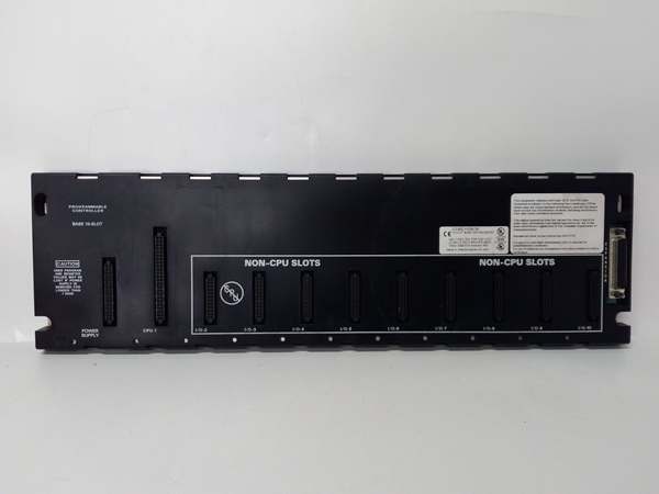
- Slot Count: 5 slots (universal—I/O and most option modules)
- Baseplate Type: Expansion I/O Baseplate (requires CPU baseplate connection)
- Voltage Rating: Powered via dedicated power supply module (IC693PWRxxx series)
- Current Capacity: Requires local power supply; internal consumption 170 mA @ 5 VDC
- Isolation: 1500 VAC isolation between logic and field circuits
- Backplane Power Bus: 5 VDC logic power, 24 VDC field power distribution
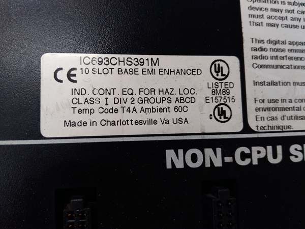
- Mounting: DIN rail or panel mount (grounded metal construction)
- Dimensions: 10.43 in. × 5.12 in. × 5.59 in. (265 mm × 130 mm × 142 mm)
- Weight: Approximately 1.8 kg (4.0 lbs)
- Operating Temperature: 0°C to 60°C (32°F to 140°F)
- Humidity: 5% to 95% non-condensing
- Connector Type: Edge connector for all Series 90-30 I/O module types
- Expansion Port: 25-pin female D-type I/O expansion connector at right end
- Maximum Cable Distance: 50 feet (15 meters) from CPU baseplate
- Expansion Limits: Up to 4 baseplates (CPUs 331/340/341) or 7 baseplates (CPUs 350+)
- Grounding: Integral grounding studs; all baseplates must share common ground
- Restricted Modules: Does NOT support PCM, ADC, BEM330, or CMM311 option modules
- Product Lifecycle Status: Discontinued by manufacturer; QUA suffix indicates qualified/refurbished quality assurance status

GE IC693CHS391
The Real-World Problem It Solves
Your main CPU baseplate runs out of slots, but you don’t need the complexity or cost of adding another CPU. The IC693CHS398QUA lets you extend I/O capacity within the same cabinet or nearby location by adding five more slots that the existing CPU manages directly. Unlike remote I/O racks that communicate over serial buses, expansion baseplates like the QUA version connect via parallel expansion cables, delivering faster communication and simpler configuration for I/O-dense applications.
Where you’ll typically find it:
- Local I/O expansion: Control cabinets where the main CPU rack is full and additional I/O modules are needed within the same enclosure
- Cabinet-adjacent expansion: Secondary racks located near the main cabinet within the 50-foot cable limit, where parallel expansion communication is preferred over serial remote I/O
- System retrofit projects: Expanding existing Series 90-30 installations where adding expansion baseplates is more cost-effective than upgrading to larger rack configurations
Bottom line: The IC693CHS398QUA provides five additional slots for I/O expansion controlled by your existing CPU—no new CPU, no complex networking, just more I/O capacity within 50 feet.
Hardware Architecture & Under-the-Hood Logic
The IC693CHS398QUA operates as an expansion baseplate in the Series 90-30 architecture, connecting to a main CPU baseplate via the expansion port rather than hosting a CPU locally. Unlike remote baseplates that use serial I/O bus communication, expansion baseplates use a parallel expansion interface that effectively extends the main CPU’s backplane bus, treating the expansion rack as a logical extension of the main rack.
-
Expansion Bus ArchitectureThe QUA baseplate connects to the CPU baseplate via a 25-pin D-type expansion connector:
- Parallel communication interface rather than serial I/O bus
- Effectively extends the main CPU backplane bus to the expansion rack
- Faster communication compared to serial remote I/O architecture
- Cable distance limited to 50 feet (15 meters) to maintain signal integrity
- Multiple expansion baseplates can be daisy-chained (CPU → Expansion 1 → Expansion 2, etc.)
-
Power Distribution SystemUnlike remote baseplates that receive power through the I/O bus cable, expansion baseplates require a local power supply:
- Dedicated power supply slot on the left side of the baseplate
- Uses IC693PWRxxx series power supplies (AC or DC input)
- Internal power consumption: 170 mA @ 5 VDC
- Power supply distributes 5 VDC logic and 24 VDC field power to all 5 slots
- Local power supply provides better voltage regulation for high-density I/O loads
-
Universal Slot ConfigurationAll 5 slots support most Series 90-30 I/O and option modules:
- Discrete I/O modules (IC693MDLxxx series)
- Analog I/O modules (IC693ALGxxx series)
- Many option modules (excludes PCM, ADC, BEM330, CMM311)
- No CPU installation—expansion baseplates are I/O onlySlots are keyed to prevent improper module installation.
-
Expansion Limitations and RestrictionsThe QUA baseplate follows standard Series 90-30 expansion rules:
- CPU 331/340/341: supports up to 4 expansion baseplates
- CPU 350+: supports up to 7 expansion baseplates
- Total cable length from CPU to last expansion rack: 50 feet maximum
- Does NOT support PCM, ADC, BEM330, or CMM311 modules (these must be in CPU baseplate)
- All baseplates in the expansion chain must share a common ground
-
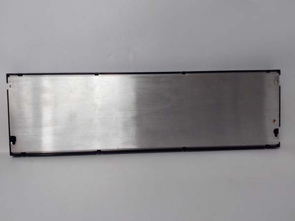
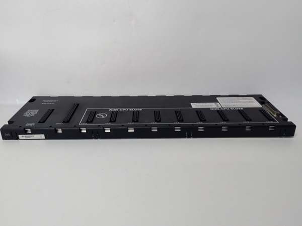
Physical Construction and MountingThe metal chassis provides EMI shielding and heat dissipation:
- DIN rail or panel mounting options
- Grounding studs for chassis ground connection
- Expansion port at right edge for daisy-chaining additional expansion baseplates
- Power supply mounting at left edge
- Standard depth (142mm) fits most industrial enclosures
-
Grounding and Shielding RequirementsProper grounding is critical for reliable expansion operation:
- All baseplates (CPU and all expansion) must share a common ground
- Chassis grounding at each expansion baseplate location
- Ground potential differences between locations can cause communication issues
- Integral grounding studs provide proper connection points
-
QUA Designation SignificanceThe “QUA” suffix typically indicates a qualified or quality-assured version:
- May denote refurbished/reconditioned units that have passed quality testing
- Could indicate a specific qualification or certification status
- Often associated with tested inventory from industrial automation suppliers
- Electrical and mechanical specifications match standard IC693CHS398
GE IC693CHS391
Field Service Pitfalls: What Rookies Get Wrong
Exceeding 50-foot cable distance
You install an expansion baseplate 60 feet from the CPU rack. Communication becomes intermittent, modules randomly fault, and you spend days chasing what appears to be module failures when it’s actually signal degradation over distance.
- Field Rule: Maximum 50 feet (15 meters) total cable length from CPU to last expansion baseplate. Measure actual cable length, not straight-line distance. Use proper IC693CBLxxx series expansion cables. If you need more distance, use remote I/O baseplates (IC693CHS398H series) instead of expansion baseplates.
Using restricted modules in expansion baseplate
You install a PCM, ADC, BEM330, or CMM311 module in the IC693CHS398QUA. The module doesn’t function, communication fails, or you damage the module because expansion baseplates don’t support these specific option modules.
- Field Rule: Expansion baseplates do NOT support PCM, ADC, BEM330, or CMM311 modules. These must be installed in the CPU baseplate only. All other Series 90-30 I/O and option modules are supported. Check module compatibility before installation.
Forgetting local power supply
You install the expansion baseplate and connect the expansion cable but don’t install a power supply. The baseplate remains dead, and you assume it’s defective or the expansion cable is faulty.
- Field Rule: Expansion baseplates require a local power supply. Unlike remote baseplates that receive power through the I/O bus cable, expansion baseplates need their own IC693PWRxxx series power supply. The expansion cable carries communication signals only.
Exceeding expansion limits
You chain 5 expansion baseplates to a CPU 340. The 5th rack is ignored, and you waste hours troubleshooting why half your I/O points are missing from the system.
- Field Rule: Respect CPU expansion limits. CPUs 331/340/341 support maximum 4 expansion baseplates. CPUs 350+ support 7 expansion baseplates. Document rack count and CPU model. If you need more expansion capacity, consider upgrading the CPU or using network I/O.
Improper daisy-chain topology
You connect expansion baseplates in a star or loop configuration instead of daisy chain. Communication fails, or some racks are ignored because the CPU doesn’t recognize them in the expected configuration.
- Field Rule: Proper daisy chain only. Connect CPU rack to expansion 1, expansion 1 to expansion 2, etc. No loops, no stars, no tee configurations. The expansion topology is fixed—deviation causes communication failures.
Mixing ground references
You install expansion baseplates in different locations with different ground references. Ground potential differences cause noise, erratic I/O behavior, or communication failures.
- Field Rule: All baseplates must share a common ground. Connect each expansion baseplate’s grounding stud to the same plant earth reference. Avoid ground potential differences between rack locations.
Using incorrect cable type
You use generic cable instead of IC693CBLxxx series expansion cables. Communication fails intermittently, and you blame the baseplates or modules when it’s actually the cable.
- Field Rule: Use only IC693CBLxxx series expansion cables designed for the Series 90-30 expansion interface. These have proper pinout, shielding, and impedance characteristics. Don’t substitute generic cable.
Overlooking software configuration
You install expansion baseplates physically but don’t update the CPU software configuration. The new slots remain unrecognized, and I/O points mapped to the expansion rack don’t function.
- Field Rule: Update hardware configuration in CPU software after physical changes. Add the new expansion baseplates and slots to the I/O table. Download updated configuration to the CPU. Physical changes without software updates result in unrecognized hardware.
Ignoring power supply sizing
You fill all 5 slots with high-current modules but install a 5-amp power supply. The supply sags under load, modules brown out, or fault unexpectedly.
- Field Rule: Calculate total module current draw across all 5 slots (5V logic + 24V field). Size the power supply for this load plus a 20% margin. For high-density racks, consider IC690PWR124 (10 amp) or split the load across multiple baseplates.
Hot-swapping modules
You attempt to remove or insert modules with power applied. Backplane transients damage components or crash the CPU, requiring system reboot.
- Field Rule: Always power down the local power supply before changing modules. These aren’t hot-swappable components. Power down the expansion baseplate, verify zero voltage, then perform module changes. Hot-swapping eventually results in component damage.
Forgetting expansion cable termination
You daisy-chain multiple expansion baseplates but don’t properly terminate the last rack. Signal reflections cause intermittent communication faults that mimic module failures.
- Field Rule: The last expansion baseplate in the daisy chain may require termination depending on the CPU model and configuration. Consult the CPU manual for termination requirements. Improper termination causes signal reflections and communication faults.
Commercial Availability & Pricing Note
Please note: The listed price is for reference only and is not binding. Final pricing and terms are subject to negotiation based on current market conditions and availability.


