
Description
Hard-Numbers: Technical Specifications
- Slot Count: 5 slots (I/O modules only—no CPU installation)
- Baseplate Type: Remote I/O Expansion Baseplate (requires IC693CBLxxx series expansion cable from CPU)
- Voltage Rating: 115/230 VAC (50/60 Hz) or 24 VDC power supply input
- Current Capacity: 10 Amps (with IC690PWR124) or 5 Amps (with IC690PWR024)
- Isolation: 1500 VAC isolation between logic and field circuits
- Backplane Power Bus: 5 VDC logic power, 24 VDC field power distribution
- I/O Bus Interface: Integral receiver for shielded twisted-pair I/O bus (IC693CBL300 series)
- Maximum Distance: 213 meters (700 feet) from CPU
- Mounting: DIN rail or panel mount (grounded metal construction)
- Dimensions: Approx. 210 mm × 132 mm × 98 mm
- Weight: Approximately 1.5 kg (3.3 lbs)
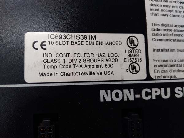
- Operating Temperature: 0°C to 60°C (32°F to 140°F)
- Humidity: 5% to 95% non-condensing
- Connector Type: Edge connector for I/O modules + I/O bus receiver connector
- Power Supply Compatibility: IC693PWRxxx series power supplies
- CPU Compatibility: Series 90-30 CPUs with I/O bus expansion capability
- Grounding: Integral grounding studs for proper chassis grounding
- Termination: Supports IC693ACC307 termination plug or built-in termination (IC693CBL302/314)
- Product Lifecycle Status: Active

GE IC693CHS391
The Real-World Problem It Solves
Running hundreds of individual field wires back to a central control room creates cable tray nightmares, voltage drops, and single points of failure that can take down your entire process. The IC693CHS392 lets you push I/O out to where the action actually happens—up to 700 feet away—and communicate back to the main CPU over a single shielded cable. You get local I/O distribution, dramatically reduced field wiring, and fault containment where a process issue takes down the local rack but not the whole PLC system.
Where you’ll typically find it:
- Remote process units: Pump stations, valve islands, or small process skids located hundreds of feet from the main control room
- Field equipment buildings: Motor control centers, terminal equipment enclosures, or MCC rooms where you need I/O close to motors but want PLC in a safer environment
- Distributed I/O architecture: Applications where I/O concentration at multiple remote points beats running miles of individual field wires back to one location
Bottom line: The IC693CHS392 is your remote I/O workhorse—5 slots of expansion capability up to 700 feet from the CPU, communicating over shielded I/O bus with full noise immunity and local fault containment.
Hardware Architecture & Under-the-Hood Logic
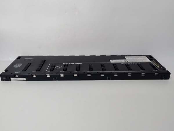
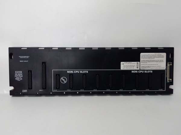
The IC693CHS392 is a remote I/O backplane with integral I/O bus receiver circuitry. Unlike a standard local baseplate, this unit receives I/O data and power over a shielded twisted-pair cable from the main CPU rack. It doesn’t need its own CPU—it’s a slave rack that the CPU treats as an extension of its own I/O system.
-
I/O Bus Communication ArchitectureThe backplane contains an I/O bus receiver that communicates with the main CPU over:
- IC693CBL300 series shielded cables (1m, 2m, 8m, 15m options)
- Belden 8107 twisted-pair construction (100Ω impedance, 70% velocity)
- Differential signal pairs for noise immunity (DFRAME, DRMRUN, DATA, DIOCLK, etc.)The receiver decodes signals from the CPU and presents them to the backplane data bus, where I/O modules pick them up as if they were local.
-
Power Distribution LogicRemote I/O requires two power considerations:
- Local power: A power supply (IC693PWRxxx) mounted on the baseplate provides 5 VDC logic power and 24 VDC field power to local I/O modules
- Bus power: The I/O bus cable itself can carry limited power for receiver electronics, but local I/O needs local supplyThe power supply connects to the backplane like a local rack, distributing clean, regulated power to all 5 slots. The I/O bus receiver taps off the local supply for its own operation.
-
Module Slot ConstraintsThis is a 5-slot I/O baseplate—you cannot install a CPU here. Only I/O modules, communications modules, or specialty cards fit. The backplane doesn’t have the circuitry to support a CPU, and the I/O bus receiver expects to talk to a remote CPU, not host one. Attempting to install a CPU is a waste of time and potential hardware damage.
-
Isolation and Grounding SystemThe metal chassis grounds your remote rack to plant earth ground. The backplane provides 1500 VAC isolation between logic circuits (module electronics) and field circuits (I/O points). Ground studs provide connection points for safety ground. The I/O bus receiver also provides isolation between the I/O bus communication lines and the local backplane, preventing ground loops from propagating back to the main CPU rack.
-
Termination RequirementsIf this is the last (or only) remote baseplate in the chain, the I/O bus must be terminated. Options include:
- IC693ACC307 Terminator Plug on the I/O bus connector
- IC693CBL302 or IC693CBL314 (15m cables with built-in termination)Failure to terminate causes signal reflections that manifest as intermittent I/O faults, especially at higher bus speeds or longer distances.
-
Addressing and ConfigurationThe CPU sees the remote baseplate as a set of expansion slots. In your configuration software, you’ll allocate slots to this remote rack, assign I/O addresses, and the CPU handles addressing transparently over the I/O bus. The backplane itself doesn’t care about addressing—it just passes data between the I/O bus receiver and the I/O modules.
-
Distance LimitationsMaximum distance from CPU to last remote baseplate is 213 meters (700 feet). This is a hard limit set by I/O bus physics—signal degradation, propagation delay, and noise susceptibility increase beyond this distance. If you need I/O farther than 700 feet, consider fiber optic repeaters, multiple CPU systems, or network-based I/O architectures (Genius Bus, Ethernet).
GE IC693CHS391
Field Service Pitfalls: What Rookies Get Wrong
Installing a CPU in remote baseplate
You try to mount a Series 90-30 CPU in IC693CHS392. The connector fits (same edge connector), but the backplane doesn’t support CPU circuitry. The CPU won’t power up properly, or worse—you damage the CPU or the backplane.
- Field Rule: IC693CHS392 is a remote I/O baseplate—I/O modules only. No CPU installation permitted. CPUs go in CPU baseplates (IC693CHS39x series with CPU support). If you need local control at the remote location, use a separate PLC system and communicate via network, not by jamming a CPU into a remote I/O rack.
Exceeding 700-foot distance limit
You chain remote baseplates beyond 700 feet from the main CPU. Signal degradation causes intermittent I/O faults, communication timeouts, or complete bus failure that mimics hardware problems.
- Field Rule: Never exceed 213 meters (700 feet) total distance from CPU to last remote baseplate. Measure and document cable runs during installation. If you need I/O beyond this limit, use fiber optic repeaters, multiple PLC systems, or network-based distributed I/O architectures.
Forgetting I/O bus termination
You install this as the last remote rack but forget to terminate the I/O bus. Signal reflections cause data errors, ghost inputs, erratic outputs, and faults that come and go with temperature or cable movement.
- Field Rule: Always terminate the I/O bus at the last remote baseplate. Use IC693ACC307 Terminator Plug or IC693CBL302/314 (15m cable with built-in termination). Never leave the bus unterminated—reflections cause faults that are hell to troubleshoot.
Improper chassis grounding
You mount the remote baseplate to a painted surface or in a plastic enclosure without bonding to plant ground. The rack floats, noise immunity is zero, and you’re chasing ghosts—inputs flicker, outputs fire randomly, modules fault for no apparent reason.
- Field Rule: The metal chassis must connect to plant ground. Scrape paint to bare metal, use star washers, and connect to your ground bus. Remote racks are especially susceptible to ground differences—bond them solidly to earth ground at the installation point.
Using wrong cable type
You try to run the I/O bus with generic shielded cable instead of Belden 8107. Impedance mismatch, inadequate shielding, and wrong propagation velocity cause communication failures that blame on modules or CPU when it’s actually the cable.
- Field Rule: Use only IC693CBL300 series cables or equivalent Belden 8107 twisted-pair for I/O bus extension. The 100Ω impedance and 70% velocity are critical. Don’t substitute—cable mismatches cause intermittent faults that are almost impossible to trace without replacing the entire run.
Daisy-chaining incorrectly
You chain multiple remote baseplates but reverse the cable orientation or skip racks in the chain. Bus communication fails, and downstream racks don’t respond while upstream racks work fine.
- Field Rule: Install cables in correct daisy-chain order. Cable from CPU → first remote baseplate. Male connector out → cable to next remote rack. Terminate only at the last baseplate. Verify each connection clicks securely and document rack numbering sequence.
Missing local power supply
You install the remote baseplate and wire the I/O bus, but forget to mount a local power supply. The backplane is dead—no 5 VDC logic, no 24 VDC field power, and no modules power up.
- Field Rule: Remote I/O baseplates require local power supplies. Mount an IC693PWRxxx power supply on the baseplate. The I/O bus carries communication, not power for I/O modules. Without local supply, you’ve got an expensive door终止.
Overloading the I/O bus
You chain too many remote baseplates or use cables that exceed the total capacitance/impedance limits. The bus becomes marginal, communication fails intermittently, and you’re chasing what looks like random module faults.
- Field Rule: Respect I/O bus limits. Total cable length ≤ 700 feet. Maximum 7 remote baseplates per CPU (CPUs 350-364) or 4 baseplates (CPUs 331-341). Don’t chain endlessly—each baseplate adds capacitance. Document rack count and total length in as-built drawings.
Hot-swapping remote baseplates
You try to add or remove a remote baseplate from a running system without killing power. I/O bus transients crash the main CPU, brown out existing modules, or damage the I/O bus receiver circuitry.
- Field Rule: Kill all power before modifying remote baseplate connections. This includes both the local power supply on the remote rack and the main CPU rack power. The I/O bus is not hot-swappable—disconnecting it live induces transients that can crash your entire PLC system.
Ignoring environmental conditions
You install the remote baseplate in an unconditioned enclosure that hits 65°C ambient, or in a location with high humidity and condensation. The electronics overheat, corrosion occurs, and you get premature failures.
- Field Rule: IC693CHS392 is rated to 60°C ambient and 95% humidity non-condensing. If your environment exceeds these, add ventilation, heat exchangers, or move the rack to a controlled location. Remote racks are often installed in harsh environments—protect them with proper enclosures and environmental control.
Commercial Availability & Pricing Note
Please note: The listed price is for reference only and is not binding. Final pricing and terms are subject to negotiation based on current market conditions and availability.


