
Description
3. Key Technical Specifications
| Parameter | Value |
|---|---|
| Module Type | FIP I/O Scanner / Bus Controller Module |
| Communication Protocol | FIP / WorldFIP |
| Data Transfer Rate | 1 Mbit/sec (1 MHz) |
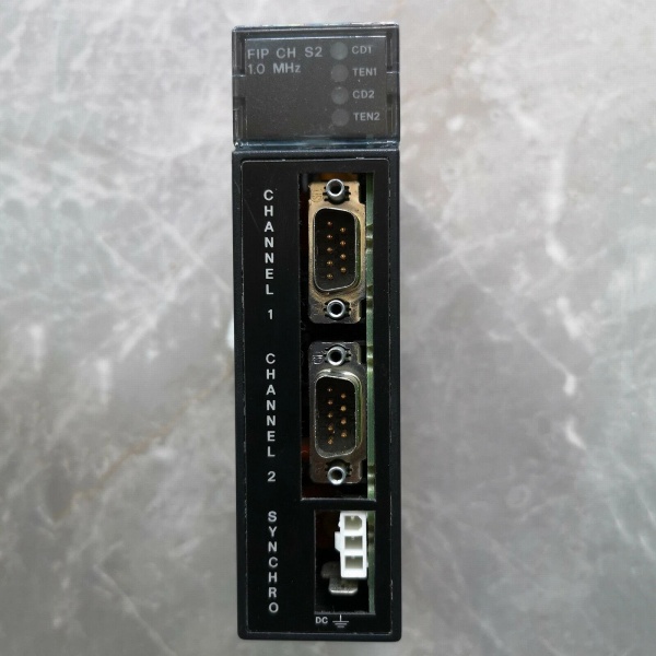
| Communication Ports | 2 × 9-pin Male D-Sub connectors |
| I/O Capacity | Up to 19 I/O modules (via dual 10-slot baseplates) |
| Bus Address Range | 0 to 127 (0x00 to 0x7F Hex) |
| LED Indicators | CD1, CD2 (Carrier Detect); TEN1, TEN2 (Transmission Enabled) |
| Backplane Current Draw | 609 mA @ 5VDC |
| Operating Temperature | 0°C to 60°C (32°F to 140°F) |
| Storage Temperature | -40°C to 85°C (-40°F to 185°F) |
| Humidity (Non-condensing) | 5% to 95% |
| Backplane Support | Universal Backplane (Slot 1 or any available slot per revision notes) |
| Synchro Connector | Molex #39-01-4031 |
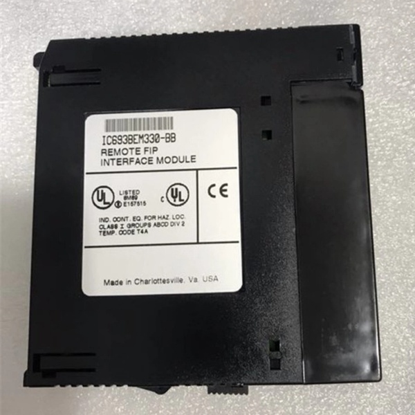
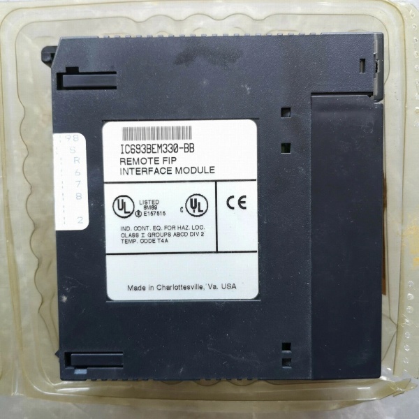
IC693BEM330
4. Product Introduction
The GE IC693BEM330 is a Remote I/O Scanner module designed for the Series 90-30 PLC platform, enabling distributed I/O architecture via the Factory Instrumentation Protocol (FIP). Acting as the bridge between the host controller and remote I/O modules, this unit manages data mapping, timing, and fault reporting while maintaining network configuration through power cycles.
The technical advantage lies in its intelligent scanning capabilities—supporting up to 19 discrete or analog I/O modules over dual 10-slot baseplates with a 1 Mbps transfer rate. It delivers deterministic control for distributed drops, critical for process industries requiring reliable communication across up to 128 devices on the FIP bus.
5. QA & Testing SOP (Transparency Building)
1. Incoming InspectionEvery incoming unit undergoes traceability verification. We check the label revision code (e.g., Rev BC/CF/DH) against the OEM datasheet and perform a physical inspection for physical damage, bent pins, or counterfeit indicators (font irregularities, incorrect screw torque). Anti-counterfeit verification includes weighing the module (0.69 lbs / 0.31 kg spec) and checking PCB component markings against known originals.
2. Live TestingWe bench-test the module in a live Series 90-30 chassis configuration. This involves powering on the backplane, verifying all four status LEDs (CD1/CD2 and TEN1/TEN2) illuminate correctly, and executing a 24-hour continuous burn-in test with simulated I/O traffic to detect thermal or intermittent faults. We verify FIP handshake with a known-good host or handheld programmer.
3. Electrical TestingUsing a Fluke 1587 Insulation Multimeter, we measure isolation resistance between the backplane and I/O circuits, ensuring it exceeds 10MΩ. Ground continuity is verified from the mounting bracket to the backplane ground reference. We also validate the 5VDC current draw stays within the 609mA ±10% tolerance under full load.
4. Firmware/Config BackupIf the unit retains memory, we record the firmware revision and capture a photo of any DIP switch configurations before reset. For refurbished units, we restore factory defaults and validate the handheld programmer interface responds correctly to configuration commands.
5. Final QC & PackagingEach module receives a QC tag documenting test results, voltage readings, and revision code. We wrap the unit in anti-static bubble wrap and place it in a conductive static-shielding bag. The outer box includes desiccant packs to prevent moisture ingress during transit.

IC693BEM330
6. Installation Pitfalls & Guide (Engineer to Engineer)
❗ Firmware Revision MismatchUsing this unit with a host CPU running incompatible firmware can cause communication timeouts or dropped scans. Always verify the host PLC firmware version matches the FIP scanner’s supported revision matrix. Consult the GFK-1505 manual for compatibility tables before swapping.
❗ DIP Switch/Jumper ErrorsIf replacing an existing module, photograph the old unit’s DIP switch positions. Incorrect settings will assign a duplicate Bus Address or set the wrong data rate (1MHz default), causing bus collisions. Ensure the address is unique on the FIP network (0-127 range).
❗ FIP Termination IssuesThe FIP bus requires proper termination at the physical ends of the trunk. Forgetting the 120Ω terminator or connecting it incorrectly will result in reflection errors. Use the Synchro connector (Molex #39-01-4031) correctly and verify cable lengths do not exceed 50 feet (15.2m) between baseplates.
❗ 5VDC Power HeadroomThe module draws 609mA from the backplane. If you are filling the rack with high-current analog modules, calculate the total load. Exceeding the power supply’s 5VDC capacity will cause intermittent failures or a brownout reset. Check the PWR330/PWR321 rating before expansion.
❗ ESD Damage During SwapI’ve seen $2000 modules destroyed by static discharge during a hot-rack swap. Always power down the chassis and ground yourself via a wrist strap before handling the unit. Touch the chassis ground plane first to discharge static potential.
Replacement Guide
- Pre-install: Log current FIP Bus Address and firmware version from the existing module. Take photos of all switch settings.
- Removal: Power down the chassis. Disconnect FIP trunk cables (note orientation). Remove the mounting screws and extract the old module carefully.
- Install: Insert the new unit into the backplane. Ensure the connector engages fully. Set the DIP switches to match your logged configuration. Secure mounting screws.
- Power-on Test: Reconnect FIP trunk cables. Power up the chassis. Observe the LEDs: CD1/CD2 should light steady when the carrier is detected, and TEN1/TEN2 should blink during data exchange.
7. FAQ (Frequently Asked Questions)
Q: Is this module hot-swappable?A: No. You cannot hot-swap this unit. It draws power from the backplane and removing it while energized risks backplane damage and can corrupt the FIP network state. Always de-energize the PLC rack before installation or removal.
Q: What warranty options are available for a discontinued part?A: Since this is discontinued by Emerson, warranty coverage depends on the supplier’s remanufacturing process. Most reputable suppliers offer a 1-2 year warranty on remanufactured units, covering board-level failures but excluding physical damage or misuse. Always request the warranty certificate.
Q: Can I use a 90-70 CPU as a host for this scanner?A: Yes. The documentation indicates that any CPU type can communicate effectively as a host on the FIP bus. You can interface this unit with Series 90-70 systems via the appropriate configuration logic, provided the protocol versions align.
Q: Does a firmware reset erase the network configuration?A: It depends on the storage type. The IC693BEM330 is designed to retain network configuration even with loss of power. However, performing a full factory reset via the handheld programmer or software will clear the stored configuration variables, forcing you to reload them.
Q: What is the lead time for this part?A: Availability varies. New Surplus stock is rare and may take 1-2 weeks. Refurbished units are typically more available, often shipping within 3-5 business days after passing QA. Given the obsolescence, verify stock status before committing to a project schedule.
Q: Does the unit support Genius I/O blocks directly?A: No. This is an FIP Remote I/O Scanner, not a Genius Bus Controller (like the IC693BEM331). It connects Series 90-30 I/O modules (discrete/analog) to an FIP network. If you need to interface with Genius blocks (IC660/IC661 series), you require a Genius Communications Module or Bus Controller, not this unit.


