
Description
3. Key Technical Specifications
| Parameter | Value |
|---|---|
| Output Channels | 8 single-ended, individually configurable |
| Output Current Ranges | 4-20 mA, 0-20 mA |
| Output Voltage Ranges | 0-10 V, -10 to +10 V |
| Resolution | 0.5 µA/bit (4-20 mA), 0.625 µA/bit (0-20 mA), 0.3125 mV/bit (voltage) |
| Absolute Accuracy | ±0.1% FS typical (current), ±0.25% FS typical (voltage) @ 25°C |
| Update Rate | 8 ms (all eight channels) |
| Maximum Compliance Voltage | VUSER –3 V to VUSER |
| User Load (Current Mode) | 0-850 Ω (VUSER = 20 V), 0-1350 Ω (VUSER = 30 V) |
| Output Load Capacitance | 2000 pF (current mode), 1 µF (voltage mode) |
| Output Load Inductance | 1 H (current mode) |
| Isolation | 250 VAC continuous; 1500 VDC for 1 minute (field to backplane) |
| Power Consumption | 110 mA from +5 V bus, 315 mA from +24 V user supply |
IC693ALG392
4. Product Introduction
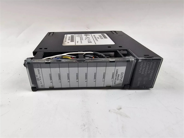
The GE IC693ALG392 is an 8-channel analog current/voltage output module designed for Series 90-30 PLC systems. Each channel is individually configurable for 0-20 mA/4-20 mA current outputs or 0-10 V/±10 V voltage outputs via software, eliminating the need for jumpers.
The module features 15-16 bit resolution (depending on range selected) and supports open wire fault detection in current mode. All eight channels are updated every 8 milliseconds. In current modes, each channel reports open-wire faults to the CPU, and outputs can maintain last state or reset to zero when system power is interrupted (if external power remains applied).
Key features include software-configurable output ranges, support for both unipolar and bipolar voltage outputs, and isolated 24 VDC power input. The module can be installed in any I/O slot of a Series 90-30 system and is fully backward compatible with existing installations.
5. QA & Testing SOP
Our QC process for this 8-channel analog current/voltage output module follows a rigorous 5-step verification:
1. Incoming Inspection: We verify part numbers and revision levels against GE/Emerson datasheets. Physical inspection checks for corrosion, bent pins, counterfeit markings, or thermal damage. We trace lot codes to confirm manufacturing origin. Photo documentation captures the terminal block configuration and LED status indicators before testing begins.
2. Live Testing: The module powers up in a Series 90-30 test rack with +5 VDC backplane power and +24 VDC external supply connected. We write known values to %AQ registers and measure output current at the IOUTx terminals using a calibrated Fluke 773 milliamp clamp meter and precision resistor. Test points include 4 mA, 12 mA, 20 mA for 4-20 mA range and 0 mA, 10 mA, 20 mA for 0-20 mA range. We test voltage mode outputs using a Fluke 87V multimeter, measuring at 0V, 5V, 10V for unipolar and -10V, 0V, +10V for bipolar ranges. We simulate open wire faults in current mode and verify fault detection reporting to the CPU. Continuous operation under full load (20 mA per channel) for 24 hours confirms stability.
3. Electrical Testing: We verify isolation resistance exceeds 10 MΩ between field side and backplane (measured at 500 VDC). Load testing confirms the device drives up to 850 Ω loads at 20 mA without voltage droop exceeding compliance limits. We verify external power input accepts 20-30 VDC and properly powers the module independently of backplane power.
4. Firmware/Config Backup: We record the exact module revision. Configuration parameters including range settings, voltage/current mode selection, and 终止 mode behavior are documented. All test data is archived with the module’s serial number for traceability.
5. Final QC & Packaging: The module passes final visual inspection, receives a QC pass tag documenting measured values at key test points, and ships in anti-static packaging with the original terminal block connector. Each unit includes a test report verifying resolution, accuracy, isolation, and fault detection functionality.
IC693ALG392
6. Installation Pitfalls & Guide
❗ Inadequate External Power Supply
The IC693ALG392 requires a user-supplied 20-30 VDC external power source connected directly to the terminal block. Without this external power, the module will not operate. The backplane +24 VDC is insufficient for analog output power. Ensure the external supply provides at least 315 mA @ +24 VDC to support full load operation of all eight channels.
❗ CPU Firmware Compatibility
For CPU firmware versions 3.3 to 4.6, the module must be configured for 16 %I inputs or a Loss of Module Fault will occur. CPU firmware version 5.0 or later is required to configure the module for 8 %I inputs. Failure to set this correctly during configuration results in module communication failures.
❗ Harsh RF Interference Environment
In environments with severe RF interference, accuracy may degrade to ±1% FS for current outputs and ±3% FS for voltage outputs. The module must be mounted in a metal enclosure to meet RF susceptibility requirements as specified in the PACSystems RX3i Systems Manual.
❗ Improper Grounding and Shielding
All field connections must use twisted, shielded instrumentation cable with shields connected to GND on the module’s terminal block. The GND connection provides access to baseplate ground, ensuring superior noise rejection. Daisy-chaining shields or improper grounding introduces measurement errors and instability.
❗ Unsupported Hand-Held Programmer Configuration
Only Series 90-30 modules IC693ALG392 version C or earlier support the Series 90-30 Hand-held Programmer. Modules version BD or later cannot be configured with a Hand-held Programmer and require Logicmaster 90-30 version 5.00 or later, or CIMPLICITY Control Software version 2.00 or later.
4-Step Installation Guide:
- Pre-install: Verify CPU firmware compatibility and update if necessary. Calculate total power requirements and ensure external supply provides at least 315 mA @ +24 VDC. Plan terminal block wiring and shield grounding scheme.
- Installation: Install module in any I/O slot. Connect user-supplied +24 VDC power to terminals 1 (24VIN) and 19 (I COM). Connect shield grounds to terminal 20 (GND). Configure module using Logicmaster or CIMPLICITY software, setting output ranges and 终止 mode behavior.
- Wiring: Connect field devices to voltage (V CH 1-8) or current (I CH 1-8) output terminals. Common connections: terminal 18 (V COM) for voltage mode, terminal 19 (I COM) for current mode. Use twisted, shielded cable for all field connections.
- Power-on Test: Apply power and verify both OK and USOK LEDs illuminate. Inject test values (0%, 50%, 100% of range) and confirm %AQ register values match output measurements. Test open wire detection in current mode and verify 终止 mode behavior (hold last state or default to low).
7. FAQ
Q: What is the maximum load resistance for current outputs?
A: Maximum load resistance depends on the external supply voltage:
- 0-850 Ω at 20 VDC
- 0-1350 Ω at 30 VDC
Loads below 800 Ω are temperature-dependent and may require derating in high-temperature environments. Calculate total loop resistance including cable resistance to ensure compliance.
Q: Can I mix current and voltage outputs on the same module?
A: Yes. Each of the eight channels is independently configurable as current or voltage output via software. You can mix 4-20 mA, 0-20 mA, 0-10 V, and -10 to +10 V outputs on the same module as required by your application.
Q: How does open wire detection work?
A: In current mode, the module continuously monitors for open circuit conditions. If an open wire is detected on any channel, a fault is reported to the CPU via the %I table. The module can be configured to hold last state or reset to zero when an open wire fault is detected.
Q: What is the difference between 15-bit and 16-bit resolution?
A: Resolution depends on the selected output range:
- 15-bit operation: Used for unipolar ranges (0-20 mA, 0-10 V) where 0 corresponds to 0% output.
- 16-bit operation: Used for bipolar ranges (-10 to +10 V) where the sign bit enables negative voltage outputs.
The module automatically adjusts resolution based on the configured range during software setup.
Q: Is this module compatible with RX3i systems?
A: Yes, the IC693ALG392 is fully compatible with both Series 90-30 and RX3i systems. It can be installed in any I/O slot of an RX3i chassis and works with all RX3i CPU models. However, RX3i modules IC694ALG392 are recommended for new RX3i installations.
Q: What happens if power is interrupted to the module?
A: If system power is lost but external user power remains applied, each output will maintain its last value or reset to zero, as configured via software. If external power is also lost, all outputs reset to zero. The module supports “Hold Last State” operation for critical applications requiring fail-safe behavior.
Q: Can I reduce the number of active channels?
A: Yes, you can configure the module to scan 1-8 channels via software configurator function. This reduces update time for critical channels and lowers power consumption. Note that the Hand-Held Programmer does not support editing the number of actively scanned channels.
Q: What is the typical application for this module?
A: The IC693ALG392 is ideal for applications requiring high-density analog output, including:
- Multi-loop process control systems
- Batch processing control
- Motion control systems
- Data acquisition systems
- Test and measurement equipment
- Industrial automation panels
It is commonly used to drive control valves, variable frequency drives, positioners, and recorders in manufacturing, energy, and chemical processing industries.


