
Description
3. Key Technical Specifications
| Parameter | Value |
|---|---|
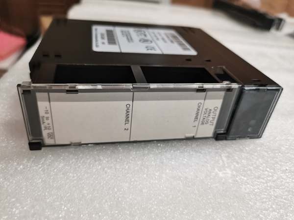
| Output Channels | 2 |
| Voltage Range | -10 to +10 VDC |
| Resolution | 2.5 mV (1 LSB = 2.5 mV) |
| Absolute Accuracy | ± 5 mV at 25°C (77°F) |
| Offset | 1 mV maximum, 0 to 60°C (32° to 140°F) |
| Update Rate | 5 ms (both channels) |
| Output Loading (Maximum) | 5 mA (2K ohms minimum resistance) |
| Output Load Capacitance | 2000 pF maximum |
| Calibration | Factory calibrated to 2.5 mV per count |
| Supply Voltage (Nominal) | +24 VDC (isolated backplane or user supply) and +5 VDC from backplane |
| External Supply Voltage Range | 18 to 30 VDC |
| External Supply Voltage Ripple | 10% |
| Isolation | 1500 volts between field side and logic side |
| Internal Power Consumption | 32 mA from +5 V supply / 120 mA from +24 V supply |
GE IC693ALG390
4. Product Introduction
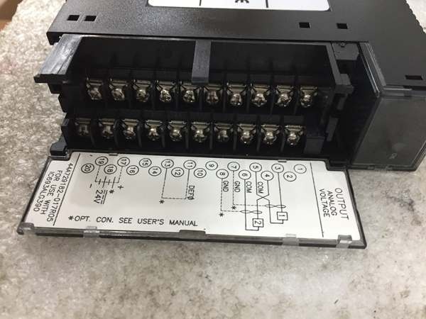
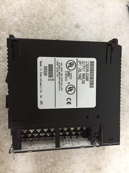
The GE IC693ALG390 is a 2-channel analog voltage output module designed for the GE Series 90-30 PLC system. Each channel converts 13-bit binary digital data to a -10 to +10 VDC analog signal with 2.5 mV resolution, making it suitable for driving field devices requiring voltage setpoints.
This unit provides 1500 V optical isolation between field wiring and logic backplane for noise immunity. A DEF0 jumper configures output behavior on CPU STOP or RESET—either default to 0 V or hold the last state. The module draws power from the PLC’s isolated +24 VDC bus or an external user-supplied source (18-30 VDC).
5. QA & Testing SOP
Our QC process for this 2-channel analog output module follows a 5-step verification:
1. Incoming Inspection: We verify part numbers against GE/Emerson datasheets. Physical inspection checks for corrosion, bent pins, counterfeit markings, or thermal damage. We trace lot codes to confirm manufacturing origin. Photo documentation captures the removable terminal block configuration and DEF0 jumper position before testing begins.
2. Live Testing: The module powers up in a Series 90-30 test rack with +5 VDC backplane power and +24 VDC external supply connected. We write known values to the %AQ registers and measure output voltage at the terminal block using a calibrated Fluke 87V multimeter. Test points include -10 V, 0 V, +10 V, and intermediate values (+3.125 V, +7.5 V). Both channels are tested simultaneously to verify the 5 ms update rate. We simulate CPU STOP and verify output behavior based on DEF0 jumper setting (hold last state or default to 0 V). Continuous operation under full load (5 mA per channel) for 24 hours confirms stability.
3. Electrical Testing: We verify isolation resistance exceeds 10 MΩ between field side and backplane (measured at 500 VDC). Load testing confirms the module drives up to 5 mA into 2KΩ loads without voltage droop exceeding ±5 mV. We verify the user-supplied power input accepts 18-30 VDC with ripple tolerance up to 10%.
4. Firmware/Config Backup: We record the exact module revision. Configuration parameters including range settings and alarm thresholds are documented. All test data is archived with the module’s serial number for traceability.
5. Final QC & Packaging: The module passes final visual inspection, receives a QC pass tag documenting measured values at -10 V, 0 V, and +10 V for both channels, and ships in anti-static packaging with the original terminal block connector. Each unit includes a test report verifying resolution, accuracy, isolation, and DEF0 jumper functionality.

GE IC693ALG390
6. Installation Pitfalls & Guide
❗ Exceeding 5 mA Output Load Capacity
The maximum output current per channel is 5 mA with a minimum load resistance of 2KΩ. Exceeding this limit causes the output voltage to clip or droop, resulting in inaccurate setpoints at the field device. Calculate total load resistance including cable resistance. If the field device requires more current or lower resistance, add an external operational amplifier buffer or consider a different output module.
❗ Incorrect DEF0 Jumper Configuration
The DEF0 jumper on the removable terminal block determines output behavior when the CPU enters STOP or RESET mode. With jumper installed, outputs default to 0 V—this drives valves to their fail-safe positions. With jumper removed, outputs hold their last state—this maintains current output values until power is cycled. Failing to document the existing jumper position before removal can result in unexpected equipment behavior during CPU 终止s. Always photograph the terminal block before extraction.
❗ Missing User-Supplied +24 VDC Standby Power
While the module operates from the PLC’s isolated +24 VDC backplane supply, connecting an external user-supply (18-30 VDC) provides redundancy. If the PLC’s internal supply fails and Hold Last State is selected, the external supply maintains output voltage, preventing process drift. Without this standby, loss of PLC power causes outputs to drop regardless of jumper setting.
❗ Capacitive Loading and Cable Length Issues
Maximum output load capacitance is 2000 pF. Exceeding this limit—typically through long unshielded cables or multiple devices paralleled on one output—causes output instability, ringing, or oscillation. Use twisted-pair shielded instrumentation cable with shields connected to GND on the terminal block. Keep cable runs under 500 feet (150 meters) for voltage signals; longer runs require signal conditioners or current converters.
❗ Backplane Power Headroom Depletion
The device draws 120 mA from the +24 V supply in addition to the 5 mA per channel output current. In racks with multiple analog modules, the PLC power supply may reach its capacity limit, causing voltage sag and affecting all rack modules. Calculate total +24 V load and verify the power supply (typically IC693PWR321, PWR330, or PWR331) has adequate headroom. Add 20-30% margin for reliability. If the backplane supply is marginal, connect the module’s external user-supply terminals to a dedicated +24 VDC source.
4-Step Replacement Guide:
- Pre-install: Document the DEF0 jumper position and terminal block wiring (which field device connects to VOUT1 and VOUT2). Photograph the setup. Calculate load requirements and verify power supply capacity.
- Removal: Power down the rack and external supplies. Disconnect field wiring from the terminal block. Remove the failed module and transfer the terminal block assembly to the replacement unit, maintaining jumper position.
- Install: Install the replacement module in the rack slot. Reconnect the terminal block. Ensure shield connections are properly terminated to GND on the terminal block.
- Power-on Test: Apply power and verify the LED illuminates. Write test values to %AQ registers and measure output voltages with a calibrated multimeter. Test DEF0 functionality by cycling the CPU and observing output behavior.
7. FAQ
Q: What is the difference between DEF0 jumper installed vs. removed?
A: The DEF0 jumper configures output behavior on CPU STOP or RESET. With jumper installed, outputs default to 0 V—this is the fail-safe state for most actuators (valves close or drives to zero). With jumper removed, outputs hold their last state, maintaining the last commanded analog output. This is critical for processes where maintaining current output values prevents disruption. Select based on your process safety requirements: fail-safe to zero vs. hold-last-state continuity.
Q: Can I use an external +24 VDC power supply instead of the PLC backplane?
A: Yes, and it’s often recommended for high-reliability applications. The module accepts 18-30 VDC at the IN24V and I GND terminals on the removable block. Providing external power reduces the load on the PLC’s internal supply and ensures outputs maintain state if the PLC supply fails (when Hold Last State is selected). Ensure the external supply is properly grounded and shares a common reference with the PLC backplane to avoid ground loops.
Q: Does this module support 4-20 mA current output?
A: No. This module only provides voltage output (-10 to +10 VDC). If your application requires current loop output, use the IC693ALG391 (2-channel analog current output module) which provides 0-20 mA or 4-20 mA outputs. For hybrid voltage and current requirements, mix both module types in the rack.
Q: What happens if I exceed the 5 mA output current limit?
A: The output voltage will clip or droop, and the module may overheat under sustained overload. If the field device requires more than 5 mA, you must add an external voltage-to-current converter or operational amplifier buffer between the module and the load. Never connect multiple devices in parallel to a single output without verifying total load resistance exceeds 2KΩ.
Q: Is this module still manufactured?
A: The GE Series 90-30 platform is discontinued. Most available units are New Surplus or refurbished. Verify the module revision matches your existing rack configuration. Emerson acquired GE Intelligent Platforms in 2019 and continues limited support for legacy parts, but new production has ceased.
Q: Can I swap this module with IC693ALG391 (current output)?
A: No. These modules are not interchangeable. The IC693ALG390 provides voltage output (-10 to +10 VDC), while IC693ALG391 provides current output (0-20 mA or 4-20 mA). The terminal block pinouts differ, and the PLC %AQ scaling values are not compatible. Replacing one with the other requires reconfiguring both hardware wiring and PLC program logic.
Q: What is the maximum cable length for voltage output?
A: GE does not specify a maximum cable length, but voltage signals are susceptible to noise and voltage drop over distance. For reliable operation, keep cable runs under 500 feet (150 meters) using twisted-pair shielded instrumentation cable. For longer runs or high-noise environments, convert to 4-20 mA current signals (which are immune to voltage drop) using a transmitter or use the IC693ALG391 current output module.


