
Description
3. Key Technical Specifications
| Parameter | Value |
|---|---|
| Input Channels | 1-16 single-ended or 1-8 differential (selectable) |
| Voltage Range | 0 to +10V (unipolar) or -10 to +10V (bipolar) |
| Calibration | 2.5 mV/count (0-10V) / 5 mV/count (-10 to +10V) |
| Update Rate | 6 ms (all 16 single-ended) / 3 ms (all 8 differential) |
| Resolution | 2.5 mV @ 0-10V (1 LSB = 2.5 mV) |
| Resolution | 5 mV @ -10 to +10V (1 LSB = 5 mV) |
| Absolute Accuracy | ±0.25% of full scale @ 25°C (77°F) |
| Absolute Accuracy (Operating Temp) | ±0.5% of full scale over specified range |
| Linearity | < 1 LSB |
| Isolation | 250 VAC continuous; 1500 VAC for 1 minute (field to backplane/logic side) |
| Common Mode Voltage (Differential) | ±11 V (bipolar range) |
| Cross-Channel Rejection | > 70 dB from DC to 1 kHz |
| Input Impedance | >500 KΩ (single-ended mode); >1 MΩ (differential mode) |
| Input Filter Response | 41 Hz (single-ended mode) / 82 Hz (differential mode) |
| Internal Power Consumption | 112 mA max from +5 VDC bus |
| Internal Power Consumption | 41 mA max from isolated +24 VDC supply |
| Weight | 0.88 lbs (0.40 kg) |
| Country of Origin | United States |
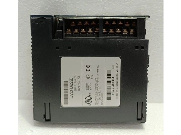
IC693ALG222E
4. Product Introduction
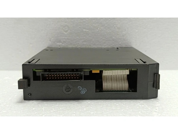
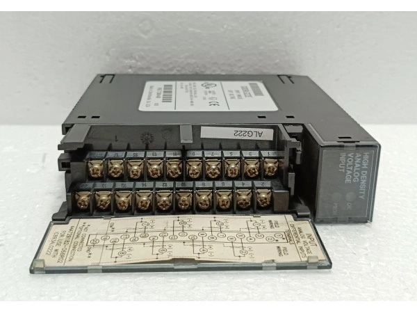
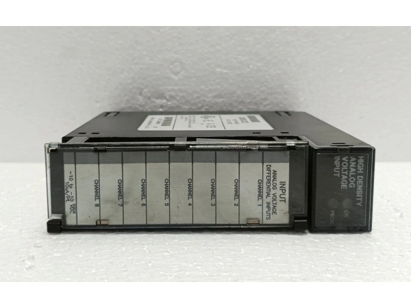
The IC693ALG222E is a revision E variant of the GE Fanuc Series 90-30 16-channel analog voltage input module, offering the same high-performance analog input capabilities as the base IC693ALG222 with the benefit of a mid-production hardware revision. This module provides up to 16 single-ended input channels or 8 differential input channels, with each channel individually configurable for either unipolar (0 to +10V) or bipolar (-10 to +10V) voltage ranges. Factory-calibrated for precision, the module delivers ±0.25% accuracy at room temperature and scales to ±0.5% across the specified operating temperature range.
The revision E variant represents one of the evolutionary improvements in the IC693ALG222 product line. While core electrical specifications remain identical to earlier revisions (A through D), revision E may incorporate minor manufacturing refinements, firmware updates, or component optimizations. The module supports high-density installations where rack space is at a premium. Differential mode provides superior noise immunity for long cable runs or electrically noisy environments, while single-ended mode maximizes channel count when signal integrity is less critical. Update rates of 6 ms for single-ended and 3 ms for differential configurations ensure responsive data acquisition for process control applications.
LED indicators—MODULE OK and POWER SUPPLY OK—provide at-a-glance status diagnostics, and optional alarm thresholds can be configured per channel for early fault detection. Configuration is handled through Logicmaster 90-30/20/Micro programming software or via CIMPLICITY Control configurator, with parameters stored in the PLC. The module uses %AI references for analog data and %I references for status and alarm information, with configurable %I size from 8 to 40 bits depending on alarm requirements.
5. QA & Testing SOP
Our QC process for this IC693ALG222E revision module follows a rigorous 5-step verification:
1. Incoming Inspection: We verify part numbers and revision levels against GE/Emerson datasheets, confirming the “E” revision designation on the module label. Physical inspection checks for corrosion, bent pins, counterfeit markings, or thermal damage. We trace lot codes and date codes to confirm manufacturing origin and ensure firmware compatibility with target systems.
2. Live Testing: The module powers up in a Series 90-30 test rack with both +5 VDC and isolated +24 VDC supplies connected. We apply known voltage inputs across all configured channels at 0%, 50%, and 100% of scale for both unipolar and bipolar ranges. A calibrated Fluke 87V multimeter verifies readings within ±0.25% of expected values. All enabled channels are scanned simultaneously for 4 hours under full load to confirm stability. Revision-specific firmware quirks are tested against known issues from earlier revisions.
3. Electrical Testing: Insulation resistance exceeds 10 MΩ between field side and logic side (measured at 500 VDC). We verify continuity on all backplane pins and check for short circuits between channels. Common mode rejection is verified by applying ±11V to differential inputs and confirming no reading degradation.
4. Firmware/Config Backup: We record the exact firmware version and revision (confirming E revision). Photo documentation captures the terminal block configuration and any jumper settings before testing begins. Configuration parameters are backed up for reference.
5. Final QC & Packaging: The module passes final visual inspection, receives a QC pass tag documenting measured values for all input points and revision information, and ships in anti-static packaging. Each unit includes a test report verifying accuracy across all configured channels with specific callout of the E revision status.

IC693ALG222E
6. Installation Pitfalls & Guide
❗ Missing Isolated +24 VDC Supply
This module requires isolated +24 VDC from the backplane (41 mA maximum) to power the on-board converters that supply isolated ±5V to the user-side circuitry. Without this supply, the POWER SUPPLY OK LED will not illuminate and inputs will not function. Verify your rack’s +24 VDC supply can handle the additional 41 mA load per module.
❗ Overlooking Revision Compatibility When Mixing Modules
The IC693ALG222E is fully electrically compatible with earlier revisions (A-D, F-Z) in terms of basic operation. However, if you’re mixing revisions in the same rack, ensure your PLC firmware can handle the specific revision’s firmware level. Some older CPU firmware versions may have compatibility quirks with later revisions. Test mixed-revision configurations carefully before deployment.
❗ Exceeding Common Mode Voltage Limits (Differential Mode)
In differential mode, the summation of the differential input voltage, common mode voltage, and noise must not exceed ±11 volts relative to COM. Exceeding this limit causes inaccurate readings or potential input damage. Calculate worst-case common mode voltage in your application and verify it stays within ±11V.
❗ Forgetting %I Size Configuration
When using alarm functionality, the %I Size must be configured (8, 16, 24, 32, or 40 bits) to allocate sufficient %I references for alarm status bits. The default of 8 bits only supports Module OK and Power Supply OK status. If you configure alarm thresholds on channels 5-16, you must increase %I Size accordingly or alarms won’t report to the PLC.
❗ Assuming Revision Differences Affect Basic Specs
The E revision does not change the fundamental electrical specifications (channels, voltage ranges, accuracy, power consumption). Don’t recalibrate your PLC program assuming different scaling factors. The revision is primarily a manufacturing/firmware refinement, not a specification change. Use the same configuration parameters as earlier revisions.
4-Step Replacement Guide:
- Pre-install: Document the channel configuration (single-ended vs. differential, active channel count, voltage ranges per channel, and alarm thresholds). Photograph the terminal block wiring and note the existing module’s revision (check label). Verify the replacement E revision is compatible with your system firmware.
- Removal: Power down the rack. Disconnect the terminal block wiring. Remove the failed module.
- Install: Install the replacement IC693ALG222E module in the same slot. Reconnect the terminal block according to the documented wiring scheme.
- Power-on Test: Apply power. Verify both LEDs illuminate (MODULE OK and POWER SUPPLY OK). Apply known test voltages to each configured channel and verify %AI values match expected readings within tolerance. Check alarm functionality by intentionally exceeding configured high/low limits.
7. FAQ
Q: Does the E revision have different specifications than earlier revisions?
A: No. The IC693ALG222E has identical electrical specifications to earlier revisions (A-D) and later revisions (F-Z) in terms of channels, voltage ranges, accuracy, power consumption, and isolation. The revision letter represents manufacturing or firmware refinements, not specification changes. Use the same configuration parameters for any revision.
Q: Can I mix IC693ALG222E with other revisions in the same rack?
A: Yes, electrically all revisions are compatible. However, ensure your PLC firmware can handle the specific revision’s firmware level. Some older CPU firmware versions may have compatibility quirks with certain revisions. Test mixed-revision configurations carefully, especially if your system firmware hasn’t been updated recently.
Q: What specific improvements does the E revision offer over earlier revisions?
A: GE/Emerson does not publicly document the specific changes between revision letters. Changes typically involve minor component optimizations, manufacturing process refinements, or internal firmware tweaks. If a revision addressed a known issue, it would be documented in service bulletins. Unless you’re troubleshooting a revision-specific problem, treat E as functionally equivalent to other revisions.
Q: Does this module support hot-swapping?
A: No. This unit is not rated for hot-swap. Removing it with power applied risks backplane communication faults and potential module damage. Always power down the rack before replacement.
Q: Can I configure different voltage ranges on different channels?
A: Yes. Each channel can be individually configured for either 0 to +10V (unipolar) or -10 to +10V (bipolar). However, the module operates in either single-ended or differential mode globally—you cannot mix single-ended and differential channels on the same module.
Q: What’s the difference between single-ended and differential modes?
A: Single-ended mode uses a single input wire per channel referenced to a common (COM), supporting up to 16 channels. It’s simpler but more susceptible to noise. Differential mode uses two wires per channel (positive and negative), supporting up to 8 channels with superior noise rejection and common mode voltage capability up to ±11V. Use differential for long cable runs or electrically noisy environments.
Q: Will this module work in a Series 90-70 rack?
A: No. This unit is designed specifically for Series 90-30 backplanes. Mechanical and electrical interfaces differ between Series 90-30 and 90-70. You need Series 90-70 specific modules (IC697ALGxxx series) for 90-70 racks.
Q: Is the IC693ALG222E still manufactured?
A: The Series 90-30 platform is mature and has been discontinued by GE/Emerson. Most available units are New Surplus or refurbished stock. Verify firmware compatibility with your existing modules before installation.
Q: What does the “LT” suffix mean compared to “E”?
A: The “E” is a GE/Emerson factory revision letter. The “LT” suffix (as in IC693ALG222LT) is not a factory revision—it’s a value-added service from certain suppliers indicating the module has undergone additional low-temperature testing. Electrically, IC693ALG222E and IC693ALG222LT are the same module type. You could have IC693ALG222ELT (an E revision that has been low-temperature tested).
Q: What happens if an input exceeds ±11V common mode voltage?
A: The module is rated for ±11V common mode voltage in differential mode. Exceeding this limit can cause inaccurate readings, damage to input circuitry, or permanent module failure. Ensure your field signals, including any common mode offset, stay within specification.


