
Description
Hard-Numbers: Technical Specifications
- Output Channels: 4 isolated channels
- Voltage Output Range: 0-10VDC (configurable per channel)
- Current Output Range: 4-20mA (configurable per channel)
- Resolution: 12-bit (4096 counts full scale)
- Accuracy: ±0.25% of full scale at 25°C
- Load Resistance (Voltage): Minimum 1K ohm, Maximum 5K ohms
- Load Resistance (Current): Maximum 600 ohms @ 24VDC supply
- Update Rate: 1 ms per channel (all 4 channels update in 1 scan)
- Isolation: 1500 VAC optical isolation per channel (channel-to-channel and channel-to-backplane)
- Backplane Current Draw: 200 mA @ +5 VDC
- External Power Required: 24VDC for current output channels (voltage outputs use backplane +5VDC)
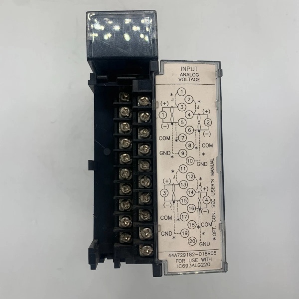
- Terminal Block: Removable 12-position terminal block
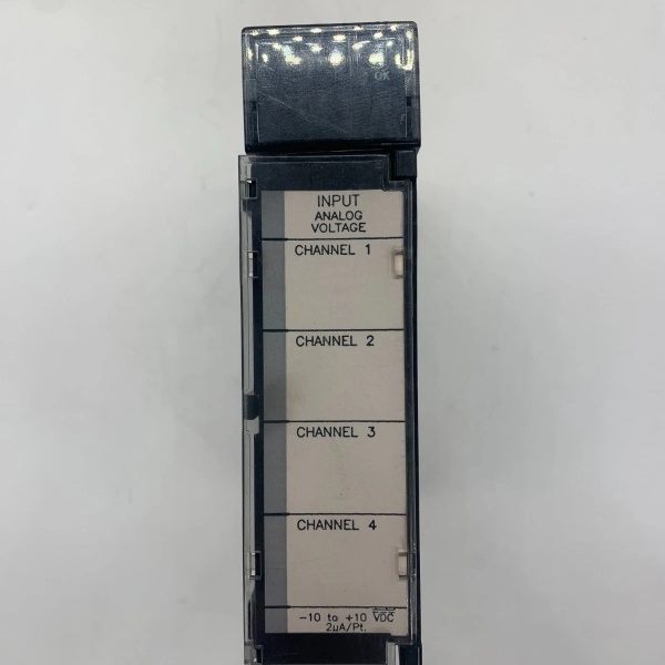
- LED Indicators: 4 individual LEDs (one per channel)
- Operating Temperature: 0°C to 60°C (32°F to 140°F)
- Wire Size: 14-22 AWG (solid or stranded)

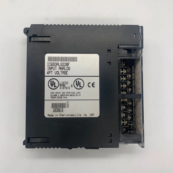
IC693ALG220
The Real-World Problem It Solves
Your Series 90-30 PLC needs to control analog field devices—valve positioners requiring 4-20mA signals, variable frequency drives needing 0-10V speed references, damper actuators needing analog setpoints. Running separate wiring for each device or using terminal boards that don’t integrate with your PLC creates additional complexity. This module gives you 4 isolated analog output channels in one package, each configurable as voltage or current per channel, with individual LED indicators for troubleshooting. You terminate all 4 analog devices at one module, and the PLC drives outputs through the backplane.
Where you’ll typically find it:
- Process Control Loops: PID control loops controlling control valves through 4-20mA positioners, flow control valves, pressure regulators requiring analog setpoints
- Drive Control Applications: Variable frequency drives and servo drives requiring 0-10VDC speed references from PLC control logic
- HVAC and Building Automation: Damper actuators, variable air volume controllers, and heating control valves requiring analog output signals
Bottom line: It’s your Series 90-30 analog output gateway—4 isolated channels with configurable voltage/current outputs, eliminating separate terminal boards and simplifying analog control wiring.
Hardware Architecture & Under-the-Hood Logic
The IC693ALG220 plugs into any Series 90-30 I/O slot and communicates with the PLC backplane via standard rack communication. The module contains 4 independent output circuits, each with a digital-to-analog converter (DAC), output amplifier, optocoupler for isolation, and LED indicator. Each channel can be configured independently as 0-10VDC voltage output or 4-20mA current output. The module requires external 24VDC power for current output channels; voltage outputs use backplane +5VDC. The PLC writes analog values to %AQ addresses mapped to each channel, and the module converts digital values to analog signals.
-
Output Channel Architecture: Each of the 4 channels has an identical circuit architecture with independent DAC, output amplifier, and isolation. The DAC receives a 12-bit digital value from the backplane (0-4095 counts corresponding to 0-100% output). The output amplifier scales the DAC output to either 0-10VDC or 4-20mA based on configuration. An optocoupler provides galvanic isolation between the backplane logic and field output, protecting the PLC from ground loops and voltage spikes on field wiring.
-
Voltage Output Mode (0-10VDC): When configured for voltage output, the output amplifier generates a 0-10VDC signal from the 12-bit DAC. The voltage output source is derived from the backplane +5VDC supply through an internal DC-DC converter, providing regulated 10V reference. External load impedance must be between 1K ohm (minimum) and 5K ohms (maximum). The voltage output can drive most VFDs and actuators with high-impedance inputs. Output accuracy is ±0.25% of full scale.
-
Current Output Mode (4-20mA): When configured for current loop output, the output amplifier operates as a current source, driving 4-20mA through the external field device. Current output requires external 24VDC power connected to the module’s power input terminals. The module regulates current flow to maintain the requested mA value regardless of load resistance (up to 600 ohms max). The 4mA floor (live zero) provides fault detection—if current drops below 4mA, the field device can detect a broken wire or failed module.
-
Channel Isolation: Each of the 4 channels is optically isolated from the backplane and from each other. This prevents ground loops between field devices and eliminates common-mode noise issues. Channel-to-channel isolation allows each output to reference different ground potentials without interference. Isolation rating is 1500 VAC per channel—adequate for most industrial environments.
-
Backplane Data Exchange: The PLC writes analog output values to %AQ addresses mapped to each channel. Each channel uses one %AQ word (16 bits) but only the lower 12 bits are used for DAC resolution. The PLC can write values from 0-4095 (full scale). The module updates all 4 channels simultaneously within 1 ms of backplane data receipt. No special programming is required—standard %AQ writes drive the outputs.
-
LED Status Indication: Each channel has a dedicated green LED on the module front panel. The LED illuminates when the channel is driving an output value above minimum threshold (above 4mA for current, above 0.5V for voltage). The LED provides visual confirmation that the channel is actively driving an output. If the LED is dark, either the PLC is writing minimum output, or a fault condition exists (overload, open circuit, loss of external power).
-
External Power Requirements: Current output channels (4-20mA) require external 24VDC power supplied to dedicated power input terminals on the terminal block. This external power sources the current loop circuitry. Voltage output channels (0-10VDC) do not require external power—they use backplane +5VDC through an internal DC-DC converter. Mixing voltage and current configurations on the same module is supported—connect external 24VDC if any channel is configured for current output.
-
Output Update Rate: All 4 channels update simultaneously within 1 ms of backplane data receipt. This 1 ms update rate is fast enough for most control loop applications. The module uses a sample-and-hold circuit to maintain output values between backplane updates. Output drift between updates is negligible—typically less than 0.1% of full scale.
-
Overload and Fault Protection: Each output channel includes overload detection and protection. If the load resistance is too low (short circuit) or too high (open circuit for current), the channel detects the fault and can report it via diagnostic %I words. For current outputs, an open circuit causes current to drop below 4mA—the live zero floor provides automatic fault detection to field devices. Voltage outputs tolerate short circuits gracefully, limiting output current to protect the channel.
-
Removable Terminal Block: The module uses a removable 12-position terminal block for field wiring connections. Each channel uses two terminals (output and common return for voltage, loop out and loop return for current). The power input terminals (24VDC + and -) are on the same terminal block. Removable design allows module replacement without disturbing field wiring—disconnect terminal block, replace module, reconnect terminal block.
IC693ALG220
Field Service Pitfalls: What Rookies Get Wrong
Forgetting external 24VDC for current outputs
You configure channels for 4-20mA current output but don’t connect external 24VDC power to the module. Current outputs don’t drive, LEDs stay dark, and field devices see 0mA. You assume the module is defective.
Field Rule: Current output channels (4-20mA) require external 24VDC power connected to the module’s power input terminals. Voltage outputs (0-10VDC) use backplane +5VDC and don’t need external power. Connect 24VDC power if any channel is configured for current output. Verify polarity (+ and – terminals) before energizing. No external power equals no current output.
Exceeding load resistance limits
You wire a 1000-ohm load to a 4-20mA current output. The external 24VDC can’t drive enough voltage to maintain 20mA through 1000 ohms (requires 20V). Output saturates, and you get less than expected current. You chase calibration issues that are actually load problems.
Field Rule: Current outputs can drive maximum 600 ohms load at 24VDC supply. Calculate required voltage (I × R) and verify external power can supply it. For 1000 ohms at 20mA, you’d need 20V—marginally possible with 24VDC but leaves no headroom. Keep loads under 600 ohms for reliable operation. Voltage outputs need 1K-5K ohm loads—outside this range causes inaccuracy or inability to drive.
Mixing commons between isolated channels
You wire multiple field devices sharing a common return on isolated channels. Ground loops occur, and outputs drift or become inaccurate. You think the module is defective.
Field Rule: Each channel is isolated for a reason—use separate commons for each channel or ensure all field devices share exactly the same ground reference. Never tie isolated channel commons together unless you’re certain all field devices reference the same ground potential. Isolation prevents ground loops—don’t defeat it by wiring commons together without understanding grounding implications.
Assuming 12-bit resolution is unlimited precision
You try to position a valve to 0.1% accuracy using the 4-20mA output. The 12-bit DAC provides only 4096 steps over 4-20mA (approximately 0.024% per step). You can’t reliably achieve 0.1% positioning with this resolution.
Field Rule: 12-bit resolution provides 4096 counts full scale—approximately 0.024% resolution. Calculate required precision for your application. If you need finer than 0.1% accuracy, consider a higher-resolution module (14-bit or 16-bit) or use digital position feedback. Don’t assume unlimited precision from 12-bit DACs—resolution limits achievable accuracy.
Using undersized external power wiring
You use 24 AWG wire for the external 24VDC power connections. Multiple channels at 20mA each draw significant current, voltage drops occur, and outputs become inaccurate.
Field Rule: Use adequately sized wire for external 24VDC power connections. Calculate total current draw for all current output channels (4mA minimum, 20mA maximum per channel). Size wire to minimize voltage drop under maximum load. 16-18 AWG is typical for power connections. Undersized wire causes voltage drop and output inaccuracy—calculate before wiring.
Neglecting calibration verification
You install the module and assume outputs are accurate without verification. A valve positioner requires 12mA for mid-position but receives 11.6mA because the module has a calibration error. Process control suffers.
Field Rule: Verify output accuracy with a multimeter before commissioning. Test each channel at minimum, mid-scale, and maximum output values. Compare measured values to expected values. Verify calibration accuracy is within ±0.25% spec. If outputs are out of spec, the module may need calibration (if field-calibrable) or replacement. Don’t assume factory calibration is perfect—verify before deployment.
Overlooking open circuit detection with 4-20mA
You don’t implement open circuit detection in your PLC logic. A wire breaks on a 4-20mA channel, current drops to 0mA, and the field device (valve positioner) fails to a safe state. You never detect the fault.
Field Rule: 4-20mA current outputs provide built-in fault detection via the live zero (4mA floor). Monitor %AQ status words or analog input feedback from field devices to detect below-4mA conditions. Implement fault logic in your PLC program—below-4mA indicates open circuit or failed module. Use the live zero for automatic fault detection.
Replacing the module without documenting channel configuration
You replace a failed ALG220 with a spare module. All channels default to voltage output, but your application requires mixed voltage and current configuration. Outputs don’t work as expected.
Field Rule: Document channel configuration (voltage vs. current per channel) before module replacement. Configure replacement modules to match the original configuration before installing. Download configuration from programming software or document which channels are voltage and which are current. A fresh module defaults to voltage—re-configure before deploying. Unconfigured modules don’t match your application requirements.
Wiring polarity backwards on current loops
You wire the field device load in reverse polarity on the 4-20mA output. Current flows backwards through the device, damaging it or causing incorrect operation.
Field Rule: Observe polarity markings on the terminal block. For current loops, connect the positive terminal to the positive side of the field device and the negative terminal to the negative side. Many field devices are polarity-sensitive and can be damaged by reverse current. Verify polarity with a meter during commissioning. Reverse polarity damages devices—get it right the first time.
Commercial Availability & Pricing Note
Please note: The listed price is for reference only and is not binding. Final pricing and terms are subject to negotiation based on current market conditions and availability.


