

Description
Hard-Numbers: Technical Specifications
- Cable Type: I/O Bus Extension Cable (no built-in termination)
- Cable Length: 15 feet (4.6 meters)
- Connector Type: 25-pin D-sub male on both ends
- Termination: No built-in termination resistors
- Cable Construction: Shielded multi-conductor cable for noise immunity
- Compatible Baseplates: All Series 90-30 CPU baseplates and expansion baseplates
- Connector Gender: Male to Male
- Connector Locking: Screws for secure connection
- Maximum Cable Length in System: 15 feet per cable (IC693ACC310) when properly terminated
- System Configuration: Requires IC693ACC307 terminator plug on final baseplate
- Applications: Multi-rack I/O expansion systems with distributed I/O
- Lifecycle Status: Discontinued/Obsolete (available as surplus/refurbished)
- Revisions: Standard version only

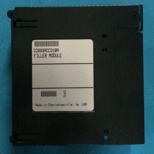
GE IC693ACC310A
The Real-World Problem It Solves
Multi-baseplate Series 90-30 systems require physical cabling to extend the I/O bus from the CPU rack to remote expansion racks. The IC693ACC310 provides the physical connection between baseplates, enabling distributed I/O architectures where I/O modules can be located closer to the field devices they control.
Where you’ll typically find it:
- Multi-rack I/O systems: Facilities with 2–8 expansion baseplates requiring I/O bus extension beyond the CPU rack
- Remote I/O installations: Applications where I/O racks need to be located near equipment or machinery, away from the main control panel
- Process automation: Food processing lines, packaging machines, material handling systems, and other industrial applications requiring distributed I/O
- Control cabinet layouts: Situations where space constraints require I/O racks to be placed in separate enclosures
Bottom line: The IC693ACC310 enables distributed I/O architectures, allowing system designers to place I/O modules where they’re most needed rather than being forced to cluster everything in a single location.
Hardware Architecture & Under-the-Hood Logic
The IC693ACC310 is a passive extension cable containing shielded conductors that carry I/O bus signals between Series 90-30 baseplates. Unlike terminated cables (IC693CBL302, IC693CBL314), IC693ACC310 has no built-in termination resistors.
-
Signal Routing:
- Carries all I/O bus signals including data, clock, and power between baseplates
- Shielded construction provides immunity to electromagnetic interference (EMI) from nearby motors, drives, and other industrial equipment
- High-quality connector contacts ensure reliable data transmission over the full 15-foot length
-
Connector Configuration:
- 25-pin D-sub male connectors on both ends
- Pin-for-pin wiring preserves signal integrity and directionality
- Screw-lock mechanism prevents vibration-induced disconnects
-
No Termination Resistors:
- Unlike IC693CBL302 and IC693CBL314, IC693ACC310 does not have built-in termination
- This allows flexibility for use in systems where the last baseplate will be terminated with IC693ACC307 terminator plug
- Prevents double termination when used in multi-baseplate systems with IC693ACC307 on the final rack
-
System Integration:
- Used to connect CPU rack to first expansion baseplate, or between successive expansion baseplates
- When multiple IC693ACC310 cables are used in a chain, only the final baseplate requires termination with IC693ACC307
- Compatible with all Series 90-30 CPU and power supply configurations
-
Signal Integrity Considerations:
- Maximum length of 15 feet minimizes signal degradation and reflection issues
- Shielding reduces noise pickup in harsh industrial environments
- Proper connector torque ensures reliable contact and maintains impedance characteristics
GE IC693ACC310A
Field Service Pitfalls: What Rookies Get Wrong
Confusing IC693ACC310 with terminated cables
Rookies assume all I/O extension cables have built-in termination resistors. They install IC693ACC310 and expect it to terminate the bus, then experience signal reflections when they omit IC693ACC307 terminator plug.
- Field Rule: IC693ACC310 has no built-in termination. You must install IC693ACC307 terminator plug on the last expansion baseplate in the chain. If you need a cable with built-in termination, use IC693CBL302 or IC693CBL314.
Exceeding maximum cable length
Rookies attempt to daisy-chain multiple IC693ACC310 cables to achieve longer distances. They connect 2–3 cables end-to-end to reach 30–45 feet total length, causing signal degradation and communication failures.
- Field Rule: Do not daisy-chain IC693ACC310 cables. Each cable-to-cable connection introduces impedance discontinuity and signal reflection. Use IC693CBL302 (25 feet) or IC693CBL314 (50 feet) for longer runs, or implement multiple expansion baseplates with proper terminators.
Mixing cable types in the same bus
Rookies use IC693ACC310 in combination with IC693CBL302 or IC693CBL314 on the same I/O bus, creating inconsistent termination and impedance characteristics.
- Field Rule: Use consistent cable types throughout the I/O bus. Either use all unterminated cables (IC693ACC310) with IC693ACC307 on the final baseplate, or use terminated cables (IC693CBL302/314) for the final cable run. Mixing cable types creates signal integrity issues.
Overtightening connector screws
Rookies use tools or excessive force to tighten the 25-pin connector screws, stripping the threads or damaging the connector housing. This leads to poor contact quality and intermittent connections.
- Field Rule: Hand-tighten connector screws until firm resistance is felt. Do not use pliers, screwdrivers, or other tools. Overtightening can permanently damage the connector and cause signal problems.
Ignoring cable routing and EMI sources
Rookies route IC693ACC310 cables near high-power drives, motors, or power cables, introducing electromagnetic interference that corrupts I/O bus signals.
- Field Rule: Maintain at least 12 inches separation from power cables and EMI sources. Route in metal conduit where possible. Use proper cable trays and avoid sharp bends that can damage the cable shield.
Bending radius violations
Rookies route cables around tight corners or pinch them in cable clamps, exceeding the minimum bending radius and damaging the shielded conductors.
- Field Rule: Maintain minimum bending radius of 10x cable diameter (typically 3–4 inches). Do not clamp cables tightly in rigid cable ties. Use flexible cable management solutions that prevent sharp bends.
Not securing cables properly
Rookies leave cables unsupported between racks. Cable weight and vibration cause stress on the connectors, leading to intermittent connections or connector failure.
- Field Rule: Support cables every 2–3 feet using cable ties or cable management systems. Use strain relief at connector ends to prevent stress on the connector pins.
Using damaged or worn cables
Rookies continue using IC693ACC310 cables with frayed shielding, exposed conductors, or damaged connectors, assuming “cable is just a cable” and won’t affect system performance.
- Field Rule: Inspect cables during preventive maintenance. Look for cuts, abrasions, damaged shielding, corroded pins, or bent pins. Replace any suspect cables immediately. Damaged cables are a major cause of intermittent I/O failures.
Failing to label cable routing
Rookies install multiple IC693ACC310 cables without labeling, making troubleshooting and future modifications difficult. When expansion systems grow, technicians cannot trace which cable connects which baseplates.
- Field Rule: Label both ends of each IC693ACC310 cable with “from” and “to” baseplate numbers. Document cable routing in system drawings. Use color-coded labels if multiple expansion buses exist in the same enclosure.
Assuming cable length has no effect on performance
Rookies install IC693ACC310 in any configuration without considering that cable length and placement affect system timing and signal integrity.
- Field Rule: Keep expansion cables as short as practical. Place expansion baseplates as close as possible to the CPU rack. Shorter cables provide better signal integrity and reduce susceptibility to EMI.
Commercial Availability & Pricing Note
Please note: The listed price is for reference only and is not binding. Final pricing and terms are subject to negotiation based on current market conditions and availability.


