
Description
Hard-Numbers: Technical Specifications
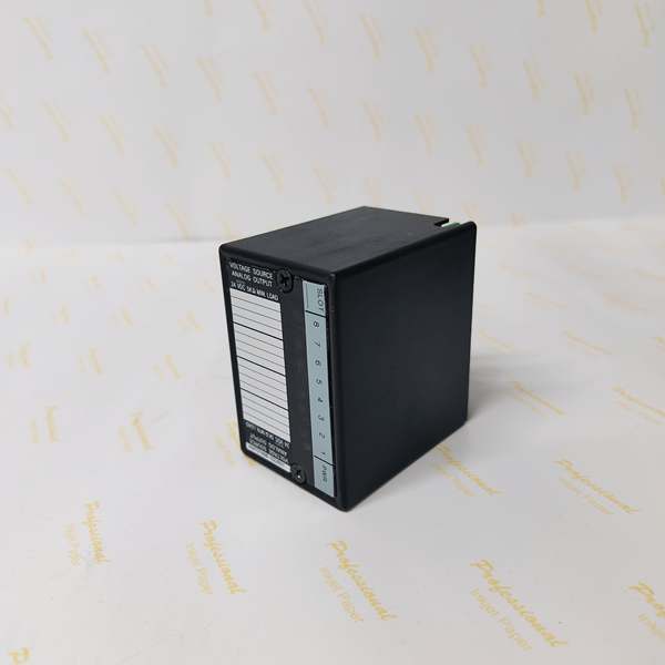
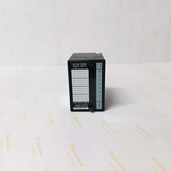
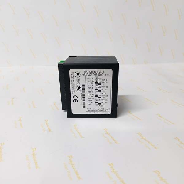
- Product Type: 8-Point Isolated Analog Voltage-Source Output Module
- Series: GE Genius Field Control / Series 90-70
- Number of Channels: 8 voltage output channels (arranged in 2 isolated groups of 4 channels each)
- Output Voltage Range: -10V DC to +10V DC per channel
- Output OVERRANGE: Up to approximately 10.25V
- Resolution: 14-bit
- Linearity: ±0.05% F.S. (typical)
- Settling Time: ≤1.5ms (to 0.1% accuracy)
- Isolation Voltage: 850Vrms (between groups and channel to ground)
- Power Supply: 18-30V DC (external power input required for outputs)
- Current Drawn from BIU: 170 mA
- Communication Protocol: Genius Bus (compatible with DF1 protocol)
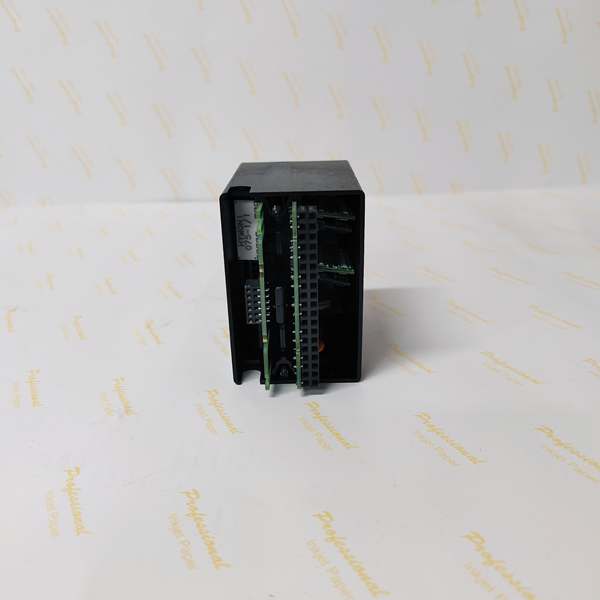
- Communication Interface: Bus Interface Unit (BIU)
- Data Types: Utilizes both word and bit data types
- Diagnostics:
- Overrange detection (outputs exceeding preset range by ±50mV)
- Underrange detection
- User power fault detection
- Undefined inputs detection
- Fault safety mode (outputs can hold last value, go to zero, or switch to preset safe value on communication failure)
- Calibration:
- Field-recalibration supported
- Factory calibration reset available
- All calibration data stored in FLASH memory
- Channel Configuration:
- Individual channel configuration including output range and scaling parameters
- Channel activation/deactivation via Hand-Held Monitor (HHM) or configuration software
- Environmental Ratings:
- Operating Temperature: -20°C to +60°C (-4°F to +140°F)
- Storage Temperature: -40°C to +85°C (-40°F to +185°F)
- Relative Humidity: 5-95% non-condensing
- Mechanical Specifications:
- Dimensions (H × W × D): 70mm × 125mm × 95mm (2.76″ × 4.92″ × 3.74″)
- Weight: 220g (0.49 lbs)
- Mounting: 35mm DIN rail (compatible with RX3i I/O base)
- Enclosure Rating: IP20 (module body)
- Certifications: UL, CE, RoHS compliant
- EMC Compliance: IEC 61000-6-2/4 standards

GE IC670ALG310
The Real-World Problem It Solves
This module converts digital control commands into high-precision analog voltage signals with galvanic isolation, enabling precise control of actuators and instruments while protecting control systems from ground loops, EMI, and high-voltage transients. Its configurable scaling and fault-safety features make it ideal for process control applications where signal accuracy and system reliability are critical.
Where you’ll typically find it:
- Process control loops in chemical/petrochemical plants driving control valves
- Temperature control systems in pharmaceutical fermentation tanks
- Flow and pressure control in water treatment facilities
- Sensor excitation and signal simulation in power generation systems
- Motor control centers with VFDs requiring voltage reference signals
Bottom line: It’s your precision analog signal generator with robust isolation and fault detection, ensuring accurate process control while protecting critical systems from hazardous conditions.
Hardware Architecture & Under-the-Hood Logic
The IC670ALG310 is a voltage-source analog output module designed for GE Genius Field Control / Series 90-70 systems. Each channel generates a programmable DC voltage output from -10V to +10V with 14-bit resolution, providing precise control for analog field devices.
Signal flow breakdown:
- Digital control commands from PLC/PAC sent to module via Genius Bus
- Module’s microprocessor processes commands and applies user-configurable scaling parameters
- Each channel’s DAC (Digital-to-Analog Converter) generates precise voltage output (-10V to +10V, 14-bit resolution)
- Outputs arranged in 2 isolated groups of 4 channels each, with 850Vrms isolation between groups and channel-to-ground
- Calibration parameters stored in FLASH memory for quick recovery and easy field recalibration
- Output circuitry provides up to 10.25V overrange capability
- Diagnostics continuously monitor for overrange, underrange, user power faults, and undefined inputs
- Fault information reported to CPU and indicated via status LEDs
- On communication failure or fault detection, outputs can maintain last value, go to zero, or switch to preset safe value
- External power supply (18-30V DC) required for output circuitry (separate from BIU power)
- Channels can be individually configured, activated, or deactivated via HHM or configuration software
- Individual channel LEDs provide immediate status indication
GE IC670ALG310
Field Service Pitfalls: What Rookies Get Wrong
Mismatched external power supplyTechnicians use incompatible power supply exceeding 30V DC or below 18V DC, causing module damage or failure to operate.
- Field Rule: Verify external power supply voltage with multimeter before connection. Use regulated 18-30V DC supply with appropriate current capacity for all active outputs.
Incorrect scaling parametersEngineers configure scaling without accounting for field device requirements, causing output range mismatches and control errors.
- Field Rule: Calculate scaling parameters based on field device specifications. Verify output corresponds to expected control signal with multimeter during commissioning.
Overlooking isolation group limitationsRookies connect outputs from different isolation groups to devices sharing a common ground, creating ground loops and signal corruption.
- Field Rule: Maintain proper isolation between groups. Ensure loads connected to different groups do not share a common ground reference. Use separate grounding points where required.
Ignoring calibration driftTechnicians assume factory calibration remains valid indefinitely, leading to output accuracy degradation over time.
- Field Rule: Perform calibration verification annually or as specified by maintenance schedule. Use field recalibration or factory calibration reset if accuracy deviation exceeds ±0.05% F.S.
Fault safety mode misconfigurationNew engineers leave fault safety settings at default without considering process safety requirements.
- Field Rule: Configure fault safety mode based on process criticality. Use “hold last value” for continuous processes requiring minimal disruption, “go to zero” for safety-critical applications, and “preset safe value” for specific shutdown scenarios.
Improper wire terminationTechs use undersized wire gauge or incorrect termination methods for analog output connections, causing voltage drop and signal degradation.
- Field Rule: Use minimum 22 AWG shielded twisted pair for analog outputs. Properly terminate shield at controller end only to avoid ground loops. Verify signal integrity with oscilloscope for critical applications.
Please note: The listed price is for reference only and is not binding. Final pricing and terms are subject to negotiation based on current market conditions and availability.


