


Description
Hard-Numbers: Technical Specifications
- Protocol Support: Genius Bus (153.6K baud)
- Port Count: 16 input circuits (2 groups of 8)
- Input Voltage: 93-132 VAC (nominal 115VAC)
- Frequency: 47-63 Hz
- Input Threshold: Programmable (25% to 85% of line voltage)
- Open Wire Threshold: Programmable (25% to 85%)
- Short Circuit Threshold: Fixed (10% to 90%)
- Input Filter: Selectable 10-100ms in 10ms increments
- Input Processing Time: 1ms typical + filter time
- Input Impedance: 11.6KΩ typical (provides 9.9mA preload at 115VAC)
- Terminal Board Rating: 5.0A per circuit
- Isolation Rating: 1500V from input to ground/serial bus
- Operating Temperature: 0°C to +60°C (+32°F to +140°F)
- Storage Temperature: -40°C to +100°C (-40°F to +212°F)
- Heat Dissipation: 28W maximum (16 inputs on at full current)
- Block Power Draw: 80mA max + 200mA max input circuit current
- Power Supply Dropout Time: 1 cycle (16.7ms @ 60Hz, 20ms @ 50Hz)
- Dimensions: 8.83″ x 3.34″ x 3.91″ (22.44cm x 8.48cm x 9.93cm)
- Weight: 4 lbs (1.8 kg)
- Mounting: Direct panel mount, supports upright or inverted orientation
- Required HMM: IC660HHM501 only

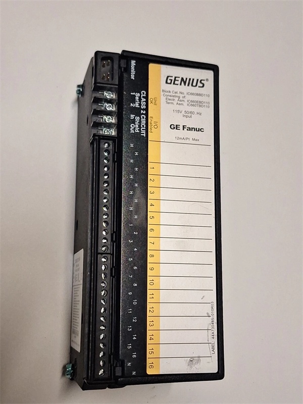
GE IC660BBD110
The Real-World Problem It Solves
This block eliminates the need for separate DC power supplies by tapping control power directly from the 115VAC field wiring. Programmable thresholds let you configure input sensitivity for different sensor types, and per-channel diagnostics detect open and shorted wires before they cause process failures. The low-leakage design reduces off-state current for safety-critical applications.
Where you’ll typically find it:
- Paper Mills: Monitoring 115VAC limit switches and selector switches on paper machine dryer sections
- Chemical Processing Plants: Interfacing with 115VAC position switches on valve actuators and control panels
- Power Generation Facilities: Reading status from 115VAC auxiliary relays and contactors in turbine control systems
Bottom-line value: Cuts wiring costs by eliminating external power supplies, reduces troubleshooting time with channel-level diagnostics, and provides flexible threshold configuration for diverse sensor applications.
Hardware Architecture & Under-the-Hood Logic
This is a standalone intelligent input block that communicates via Genius bus without requiring a baseplate or rack. It features internal microprocessor-controlled signal conditioning with programmable voltage thresholds for each group of 8 inputs. The block derives control power from the same 115VAC source used for field inputs, eliminating the need for a separate block power supply. Inputs are resistive with 11.6KΩ impedance, providing sufficient preload to activate most 2-wire proximity switches.
Internal Signal Flow:
- 115VAC field power connects to H (hot) and N (neutral) terminals, providing both control power and input voltage
- Input signals enter through terminals 5-32, divided into two groups of 8 circuits each
- Each input circuit passes through voltage divider network and resistor (Rs if shorted wire detection enabled)
- Filter stage applies programmable 10-100ms delay to eliminate noise and contact bounce
- Processed signal compared to programmable thresholds (25%-85%) to determine logic state
- Diagnostic circuits monitor for open wire conditions (via parallel resistor Rp if enabled) and shorted wire conditions (via series resistor Rs if enabled)
- Opto-isolation separates input circuitry from logic, providing 1500V isolation
- Microprocessor samples inputs at 1ms intervals, applies filter time, determines final logic state
- Input status and diagnostic data transmitted over Genius bus to controller
- Individual circuit LEDs reflect input state; Unit OK and I/O Enabled LEDs display block health and communication status
GE IC660BBD110
Field Service Pitfalls: What Rookies Get Wrong
Mixing Phases on Input Power
The block requires all inputs and block power to come from the same 120VAC phase, but techs sometimes wire inputs from different phases to the same block. This creates phase-to-phase potential through the internal common, potentially damaging circuits or causing erratic operation. I’ve seen blocks destroyed when someone connected Phase A inputs and Phase B power to the same assembly.
- Field Rule: Verify all field device connections and block power originate from the same AC phase using a multimeter before energizing. Label phase sources clearly to prevent cross-phase connections. Never mix phases on the same block—use separate blocks for different phases with proper isolation.
Daisy-Chaining Block Power Through H/N Terminals
Extra H and N terminals are provided for wiring convenience only, but techs use them as power distribution points to daisy-chain power to other blocks. This overloads the terminal board rating (5A) and can cause overheating or terminal failure. I’ve found melted terminal blocks because someone ran power through multiple blocks via the convenience terminals.
- Field Rule: Use extra H and N terminals for wiring convenience within the block only. Never daisy-chain block power to other Genius blocks or devices through these terminals. Run separate power feeders from the main distribution panel to each block, ensuring adequate wire gauge for the load.
Improper Resistor Values for Wire Fault Diagnostics
When enabling open wire or shorted wire detection, techs skip the required series/parallel resistors or use wrong values. Default thresholds require 3.9KΩ series resistor for shorted wire detection and 22KΩ parallel resistor for open wire detection on dry contacts. I’ve seen diagnostics constantly triggering false alarms because someone used 10K resistors instead of the specified values.
- Field Rule: Always install correct external resistors when enabling wire fault diagnostics. For dry contacts with default thresholds: use 3.9KΩ series resistor for shorted wire detection, 22KΩ parallel resistor for open wire detection. If thresholds are modified, calculate new resistor values per the Discrete and Analog Blocks User’s Manual. Never enable diagnostics without proper resistors.
Using Mounting Screws as Primary Ground
The block’s mounting screws should not be the sole ground connection, but techs rely on them exclusively. If paint or oxidation prevents good ground contact, the block floats without proper grounding, creating shock hazard and potential communication issues. I’ve found blocks with floating grounds because no one connected the dedicated ground screw to the ground bus.
- Field Rule: Connect the green ground screw directly to the plant ground system using minimum AWG #12 wire. Do not rely on mounting screws alone for ground integrity. Use star washers on mounting screws to improve contact, but treat them as secondary ground only. Verify ground continuity with a multimeter after installation.
Wrong Filter Settings Cause False Inputs
Techs leave input filters at 10ms default in high-noise environments near VFDs and motors, causing electrical noise to trigger false inputs. Conversely, they set 100ms filters on safety-critical E-终止 circuits, adding unacceptable delay to emergency response. I’ve seen emergency shutdown circuits take 100+ms to respond because someone maxed out the filter to eliminate noise.
- Field Rule: Set input filters based on application type and noise level. Use 10-20ms for general-purpose inputs, 30-50ms for moderate noise environments, and 80-100ms only for extreme EMI on non-critical inputs. Never exceed 10-20ms on safety circuits like E-stops or emergency shutdowns. Measure noise levels with an oscilloscope if uncertain.
Removing Electronics Assembly Without Block Puller
When replacing the Electronics Assembly, techs try to pry it loose with screwdrivers or pliers instead of using the proper Block Puller tool (IC660BLM507). This damages connector pins or breaks the plastic housing. I’ve seen perfectly good Terminal Assemblies ruined because someone gouged the connector receptacle with a flathead screwdriver.
- Field Rule: Always use the Block Puller (IC660BLM507) to remove the Electronics Assembly. Engage tool tabs in vent slots, move to center, squeeze handle, and pull upward. Never use screwdrivers, pliers, or makeshift tools—this is a guaranteed way to damage the block. If unusual resistance is encountered, 终止 and inspect for obstacles before forcing.
Commercial Availability & Pricing Note
Please note: The listed price is for reference only and is not binding. Final pricing and terms are subject to negotiation based on current market conditions and availability.


