

Description
Hard-Numbers: Technical Specifications
- I/O Channels: 16 configurable discrete circuits (each: input/tristate/output)
- Input Voltage Range: 18-56 VDC
- Output Voltage: 24/48 VDC source-type outputs
- Load Current: 2A per channel
- Input Response Time: 1.7ms + filter time
- Output Response Time: 1.0ms
- Input Filter Time: 5-100ms (software selectable)
- Input Impedance: 1.8kΩ (24VDC) / 5.6kΩ (48VDC) typical
- Power Supply: 24/48 VDC (tapped from field device voltages)
- Operating Voltage Range: 18-56 VDC
- Power Consumption: 150mA typical / 300mA maximum
- Heat Dissipation: 68.8W maximum (all 16 outputs at 2A)
- Power Supply Dropout Time: 10ms
- Isolation: 1500V block-to-block
- Diagnostics: Short circuit, overload, overtemperature, open wire, failed switch, no-load detection
- Status LEDs: Unit OK, I/O Enabled, individual load-side LEDs per circuit
- Operating Temperature: 0°C to +60°C
- Storage Temperature: -40°C to +100°C
- Dimensions: 8.83″ x 3.50″ x 3.94″ (22.44cm x 8.89cm x 10.00cm)
- Weight: 4 lbs (1.8 kg)
- Terminal Assembly Compatibility: IC66*TSD020 version C or later
- Communication Protocol: Genius protocol with daisy-chain capability

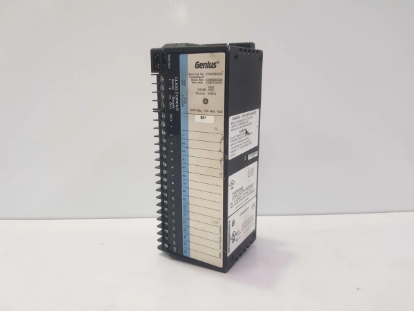
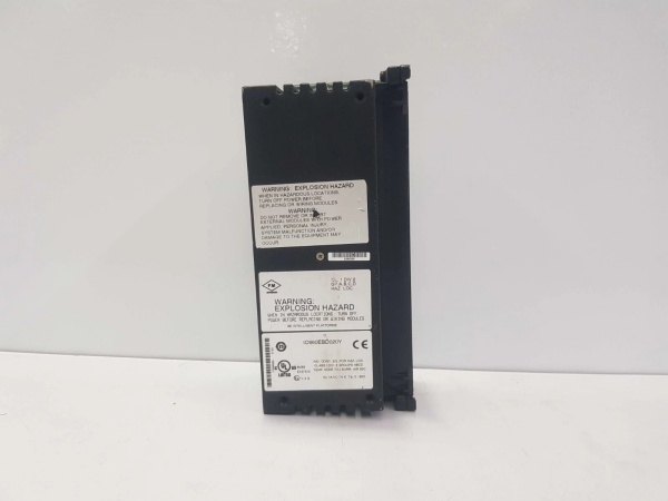
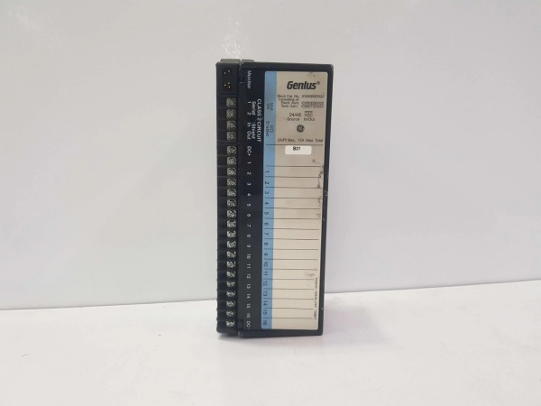
GE IC660BBD020
The Real-World Problem It Solves
This block eliminates the need for separate 24VDC power supplies by tapping control power directly from field device voltages. Each of the 16 channels can be input, output, or tristate independently, so you don’t need to buy separate input and output modules for mixed installations. Source-type wiring works with 3-wire sensors and electromechanical relays without intermediate components.
Where you’ll typically find it:
- Manufacturing assembly lines interfacing with 3-wire proximity sensors and indicator lights
- Power generation control systems with mix of discrete inputs and relay outputs
- Material handling systems with mixed sensor and actuator requirements per block
Bottom-line value: Reduces hardware count by mixing inputs and outputs on a single block, eliminates external power supplies by using field voltage, and comprehensive diagnostics catch wiring errors before they cause system failures.
Hardware Architecture & Under-the-Hood Logic
This is a source-type block where each channel can sink or source current depending on configuration. The block taps control power from the field device voltages wired to terminals, so no separate block power supply is required. All 16 circuits share a common but provide independent input, tristate, or output functionality. Advanced diagnostics monitor each circuit for shorts, opens, overloads, and overtemperature. The block communicates via Genius protocol and can daisy-chain to other Genius I/O blocks.
Internal Signal Flow:
- Field device voltage (24/48VDC) connected to terminals provides block control power
- Input circuits: Sensor signal enters through voltage divider, filtered (5-100ms), digitalized via opto-isolator
- Output circuits: Processor drives output transistors, provides source current to load up to 2A, feedback amp verifies output state
- Tristate circuits: Configured as high-impedance input for 3-wire sensor compatibility
- Diagnostics continuously monitor each circuit for short circuit, overload, overtemperature, open wire, no-load, failed switch
- Processed I/O data and diagnostic status transmitted over Genius bus to controller
- Individual load-side LEDs provide per-circuit status indication
GE IC660BBD020
Field Service Pitfalls: What Rookies Get Wrong
Exceeding Heat Dissipation Limits
The block dissipates 68.8W with all 16 outputs running at 2A, but techs install multiple blocks in sealed cabinets without ventilation. This causes thermal shutdown or premature component failure. I’ve found cabinets at 75°C with blocks in thermal cutout because nobody calculated heat load for mixed I/O configurations.
- Field Rule: Calculate total heat dissipation based on actual configuration, not maximum ratings. For high-density output applications (12+ channels active at 2A), install forced cooling or limit active outputs per cabinet. Never mount blocks in sealed enclosures without airflow. Use thermal imaging during commissioning to verify heat dissipation stays within limits.
Incorrect Filter Time Settings
Techs set input filters to 5ms for everything, then complain about noise from VFDs and welders causing false triggers. Or they use 100ms on fast-acting limit switches, causing detection delays and safety hazards. I’ve seen safety interlocks fail to trigger because 100ms filter was set on emergency 终止 inputs.
- Field Rule: Match filter time to application. Use 5-10ms for fast-acting safety inputs (E-stops, limit switches). Use 20-50ms for general-purpose inputs. Use 80-100ms only for very slow inputs or extremely noisy environments. Never sacrifice safety response time for noise reduction—use shielded cable instead.
Missing Star Washer Grounding
The manual specifies star washer grounding through mounting screws, but techs mount blocks directly to painted panels or use regular lockwashers that don’t penetrate paint. This creates high-resistance ground paths, compromising noise immunity and safety. I’ve measured ground resistance over 100Ω on blocks mounted to painted surfaces.
- Field Rule: Use star washers that penetrate paint and coating to establish metal-to-metal contact. Ensure mounting surfaces are clean and conductive. Verify ground resistance is under 1Ω between the block and main panel ground using a multimeter. Never rely on painted surfaces for ground connection.
Overlooking No-Load Detection
The block detects when an output has no load connected and reports it as a diagnostic, but techs disable this feature during commissioning to eliminate nuisance alarms on unused channels. Then they never re-enable it, so failed loads go undetected until process issues appear. I’ve found burned-out indicator lights that had been dark for weeks because no-load detection was disabled.
- Field Rule: Keep no-load detection enabled on all output channels. If you have unused outputs, configure them as inputs or tristate instead of disabling diagnostics. Monitor no-load alarms during operation—open circuits on output loads are the second most common failure mode after short circuits.
Confusing Source vs Sink Wiring
This is a source-type block where outputs source voltage to loads, but techs used to sink-type blocks wire it backward, assuming conventional PNP/NPN rules don’t apply. This causes outputs not to work or creates ground loops. I’ve seen entire panel installations wrong because the tech wired outputs assuming sink configuration.
- Field Rule: Understand this is a SOURCE block—outputs provide V+ to loads. Connect load positive to output terminal and load negative to common/ground. Inputs expect sourced voltage from field devices. Never wire loads between output and V+ as with sink blocks. Verify wiring polarity with a multimeter before energizing.
Ignoring Overtemperature Protection
The block has overtemperature protection that shuts down circuits when temperature exceeds limits, but techs assume this only happens with faulty equipment. In high-temperature environments or blocked airflow, overtemperature trips regularly, causing intermittent outages. I’ve seen plants chase “ghost” faults for months until they realized blocks were thermally shutting down.
- Field Rule: Monitor overtemperature diagnostics during commissioning and normal operation. If overtemperature alarms occur, check cabinet ventilation, ambient temperature, and heat dissipation calculations. Never disable or ignore overtemperature protection—it’s telling you something’s wrong with thermal management, not the block.
Terminal Assembly Version Mismatch
The block requires Terminal Assembly IC66*TSD020 version C or later, but techs install older A/B versions or incompatible assemblies. This causes incorrect operation or prevents the block from working. I’ve seen perfectly functional blocks labeled “faulty” because someone installed the wrong terminal assembly.
- Field Rule: Verify Terminal Assembly version before installation. Check the label on the assembly—it must show version C or later for IC660BBD020. Never mix assemblies between different block types. If upgrading from older blocks, replace the entire block, not just the Electronics Assembly.
Commercial Availability & Pricing Note
Please note: The listed price is for reference only and is not binding. Final pricing and terms are subject to negotiation based on current market conditions and availability.


