

Description
Hard-Numbers: Technical Specifications
- Function: Analog signal calibration and adjustment
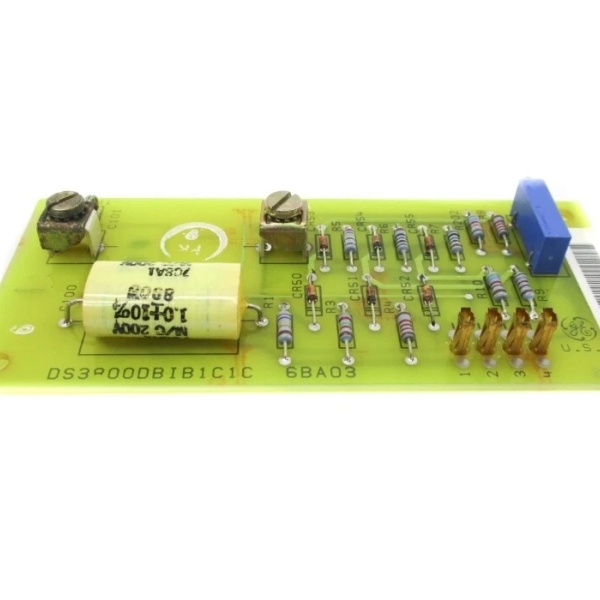
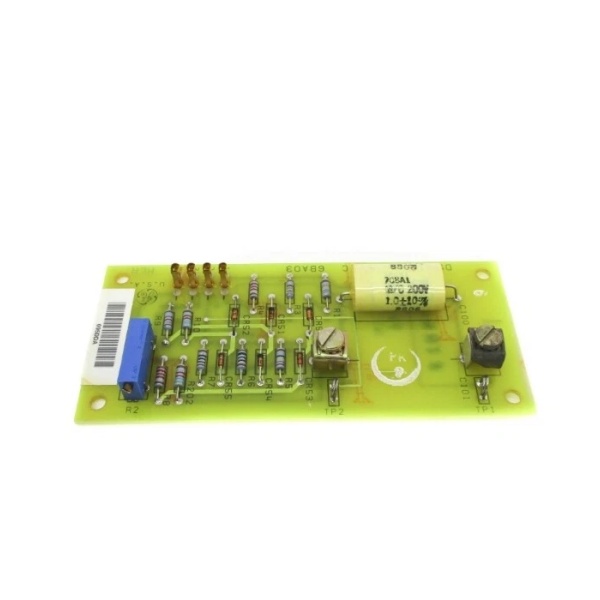
- Adjustment Points: 3 blue potentiometers (arranged in line along board surface)
- Test Interface: 1 red push-button on metal faceplate (connected via white wires)
- Protection Components: 3 red MOVs (Metal Oxide Varistors) for transient voltage suppression
- Capacitor Configuration: 1 large orange capacitor (center), 6 small paired capacitors (center vertical), 3 yellow capacitors (right side line)
- Mounting: Long metal plate fixed to left side with 4 large components
- Technology: Voltage-sensitive analog circuitry with discrete components
- Voltage Sensitivity: Yes (as specified in datasheet)
- Primary Functional Revision: C (on IC3600SVDD1C variant)
- Connector Type: Standard Mark I/II edge connector
- Series Compatibility: Mark I and Mark II Speedtronic systems
- Repair Warranty: 3 years (aftermarket refurbishment)
- Power Supply: Standard 24-28V DC from backplane

The Real-World Problem It Solves
The IC3600SVDD1 eliminates control system drift and calibration errors that cause turbine instability, inaccurate trip setpoints, and inefficient operation. By providing precise analog signal adjustment capability, it corrects offsets and scaling issues in sensor signals before they reach the processing units, ensuring speed, temperature, and pressure readings remain accurate over time and varying environmental conditions. Without this board, analog signal drift would accumulate, leading to gradual performance degradation and potential nuisance or missed trips.
Where you’ll typically find it:
- Gas Turbine Control Racks: Mounted in Mark I and Mark II Speedtronic cabinets alongside speed control, temperature control, and servo valve drive cards, providing calibration adjustment points for critical analog signals.
- Control System Commissioning: Used during initial turbine start-up and calibration procedures to align sensor readings with reference values and verify signal scaling throughout the control loops.
- Preventive Maintenance Programs: Technicians adjust potentiometers during scheduled outages to compensate for component aging and maintain signal accuracy across the control system.
Bottom-line value: This board is the field-adjustable interface that keeps aging analog control systems accurate—without proper calibration via the IC3600SVDD1, the entire turbine control system operates with cumulative error, risking both operational inefficiency and protection system unreliability.
Hardware Architecture & Under-the-Hood Logic
The IC3600SVDD1 is an analog calibrator board that provides fine-tuning capability for analog signals flowing through Mark I/II control systems. It operates as a signal conditioning and adjustment module that sits between sensor inputs and processing units, allowing technicians to add or subtract small offsets and adjust gain to correct drift. The board contains three potentiometers that create adjustable resistance dividers, enabling precise trimming of voltage and current signals. The red test button on the faceplate provides a manual test function, likely injecting test signals or verifying calibration status. Three MOVs protect the calibration circuitry from voltage spikes. The large orange capacitor provides filtering and stability for the adjustment circuits, while multiple smaller capacitors distributed across the board provide noise filtering and decoupling for various signal paths. All calibration is performed through analog circuitry—no microprocessors or digital memory involved.
Internal Signal Flow:
- Input Signal Reception: Analog signals from sensors (speed pickups, RTDs, pressure transducers, etc.) enter through the edge connector and are routed to the calibration circuitry.
- Signal Conditioning: Passive components (resistors, capacitors) filter and condition the raw signals, removing noise and establishing baseline signal levels.
- Calibration Adjustment: The three potentiometers create adjustable voltage dividers that add or subtract offset from the conditioned signals. Technicians adjust these pots to trim signal levels to match expected values.
- Reference Injection (Test Mode): When the red button is pressed, the board likely injects a known reference signal or bypasses calibration to verify signal path integrity and test downstream processing units.
- Output Distribution: Calibrated signals exit through the edge connector to control boards, alarm circuits, and processing units, ensuring accurate parameter representation throughout the system.
Field Service Pitfalls: What Rookies Get Wrong
Adjusting Potentiometers Without Baseline Documentation
Technicians frequently turn calibration potentiometers while troubleshooting without first documenting the original positions, assuming they can “readjust back later.” These three blue pots often work together for gain and offset calibration—changing one without properly adjusting the others creates misalignment across the calibration range. I’ve seen units drift out of calibration completely because a tech made incremental adjustments during a failed start-up attempt and couldn’t restore the original settings.
- Field Rule: Always count and document potentiometer turns from the mechanical 终止 (fully counterclockwise) before making any adjustment. Take digital photos showing pot positions. Record the calibrated signal values at multiple test points before changing anything. If calibration drift is suspected, verify with a known reference signal source first—don’t adjust based on suspect readings from other parts of the system.
Ignoring MOV Status During Troubleshooting
The three red MOVs on the right side of the board provide critical surge protection for the calibration circuits. Rookies often overlook these components or don’t understand their function. A blown or degraded MOV (visible as cracking, charring, or physical deformation) will fail to suppress voltage spikes, allowing transient damage to propagate to downstream calibration potentiometers and signal conditioning circuits. This results in recurring calibration drift or intermittent signal faults that are difficult to trace back to the failed MOV.
- Quick Fix: Inspect all three MOVs visually during every board inspection—look for cracks, discoloration, bulging, or charring. If any MOV shows physical damage, replace the board or the specific MOV component (if you have the skill and replacement parts). Ensure control cabinet surge protection devices upstream are functioning properly before installing a replacement calibrator board.
Pressing the Red Test Button Under Load
The red push-button on the metal faceplate is designed for test and calibration functions, but technicians often press it while the turbine is operating to “test” the board. This button likely injects test signals or alters calibration state momentarily. Pressing it under normal operation can cause sudden signal shifts that trip alarms, shut down the turbine, or cause erratic control system behavior. The test function is intended for offline calibration verification, not online diagnostics.
- Field Rule: Never press the red test button unless the turbine is shutdown, the control system is in a safe test mode, or you are specifically performing a calibration procedure with the turbine offline and all safety overrides properly implemented. Verify with the specific Mark I/II manual for your unit’s test sequence before using this button—some systems require specific power-down sequences or jumper configurations to safely enter test mode.
Failing to Verify Signal Reference Before Calibration
A common mistake is adjusting calibration pots to match panel meter readings without first verifying that the reference source (panel meter, test set, or sensor input) is accurate. If the reference source itself has drifted or miscalibrated, adjusting the IC3600SVDD1 to match it creates a compounded error that affects the entire control chain. I’ve seen technicians chase calibration errors for hours when the actual problem was a drifted panel meter or uncalibrated test set.
- Field Rule: Always verify your reference source accuracy before performing any calibration adjustment. Use a recently calibrated multimeter or signal simulator to inject known signals and measure outputs at the IC3600SVDD1 test points. If panel meter readings disagree with your verified reference, troubleshoot the meter or its associated circuitry first—do not adjust the calibrator board to match an unverified reading.
Commercial Availability & Pricing Note
Please note: The listed price is for reference only and is not binding. Final pricing and terms are subject to negotiation based on current market conditions and availability.


