
Description
Hard-Numbers: Technical Specifications
- Network Type: VersaMax Genius Bus
- Maximum I/O Racks: 8 racks per module
- Maximum Modules per Rack: 8 modules per rack
- Total Maximum I/O Modules: 64
- Discrete I/O Memory: 1024 discrete inputs; 1024 discrete outputs
- Analog I/O Memory: 128 bytes analog input memory; 128 bytes analog output memory
- Network Data Rate:
- Extended configuration: 153.6 kbaud
- Standard configuration: 153.6 kbaud, 76.8 kbaud, 38.4 kbaud (selectable)
- Network Scan Capacity: 128 bytes input/output per scan
- Power Supply:
- 5V DC, 250 mA (from backplane)
- 3.3V DC, 10 mA (from backplane)
- Operating Temperature: 0°C to 50°C (32°F to 122°F)
- Storage Temperature: -40°C to 70°C (-40°F to 158°F)
- Humidity: 20% to 80% RH (non-condensing)
- Isolation Rating: 250V AC continuous (input to logic/frame ground)
- Terminating Resistor Options: 75, 100, 120, or 150 ohms
- Serial Bus Address Range: 0 to 31 (configurable)
- Compatible Controllers: Series 90-70, PACSystems RX7i, PACSystems RX3i
- Wiring Topology: Daisy-chain (bus) topology
- Supported Cables: Shielded twisted pair (STP) and fiber optic cables
- LED Indicators: PWR (power status), OK (module status), FAULTS (fault status), I/O ENBL (I/O enable), FORCE (forced I/O status), SBA ERR (serial bus address error), BUS B (bus status)

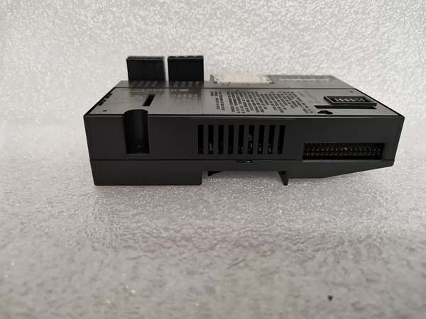
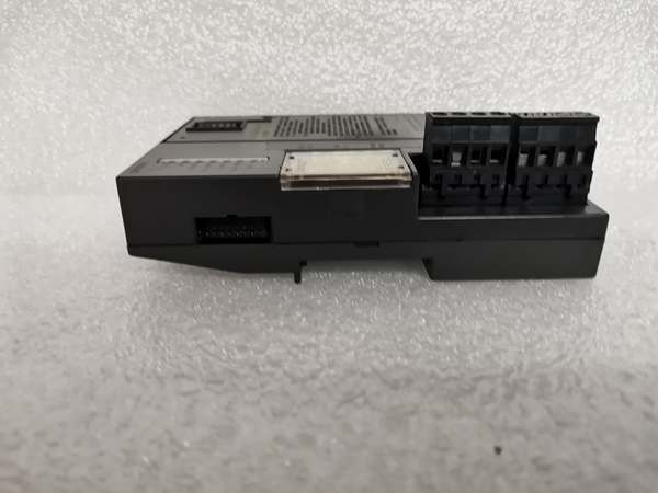
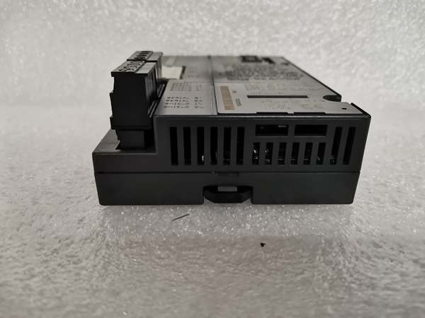
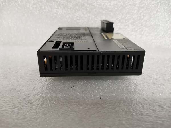
GE IC200GBI001-B
The Real-World Problem It Solves
This module solves the problem of connecting remote I/O racks to the central PLC system in large-scale distributed control applications. It allows for flexible I/O expansion without requiring additional PLC CPUs, while the dual bus terminals provide redundant communication paths to ensure high system availability. The configurable baud rates and daisy-chain topology simplify network layout and integration into existing control systems.
Where you’ll typically find it:
- Large manufacturing facilities with multiple production lines distributed across different areas
- Chemical plants with hazardous locations requiring remote I/O installations
- Power distribution systems monitoring multiple substations from a central control room
- Water treatment plants monitoring remote well pumps and tank levels
- Large-scale HVAC systems with multiple unit controllers
Bottom line: It’s the backbone of distributed control systems that require reliable, high-performance I/O communication over extended distances.
Hardware Architecture & Under-the-Hood Logic
The IC200GBI001-B is a VersaMax Genius Network Interface Unit that connects up to 8 racks of I/O modules to the VersaMax PLC system. It features dual bus terminals for redundant communication, with configurable serial bus address from 0 to 31. The module supports daisy-chain topology with terminating resistors from 75 to 150 ohms, and can be installed horizontally or vertically on DIN rails.
Signal flow breakdown:
- I/O modules (discrete, analog, RTD, thermocouple) connected to VersaMax I/O racks
- Genius Network Interface Unit (IC200GBI001-B) mounted on each rack, configured with serial bus address and baud rate
- Daisy-chained communication using shielded twisted pair or fiber optic cables, with terminating resistors at each end
- Primary and redundant bus terminals for fault-tolerant communication
- Network communication with central PLC controller (Series 90-70 or PACSystems RX3i/RX7i) using Genius protocol
- I/O scanning and data transfer (128 bytes input/output per scan)
- Diagnostic LEDs provide real-time status updates for power, module health, faults, and bus status
- Enhanced Diagnostics Mode (EDM) provides user diagnostic data for troubleshooting
GE IC200GBI001-B
Field Service Pitfalls: What Rookies Get Wrong
Incorrect terminating resistor valueTechs use 120 ohm resistors for fiber optic cables, which should use 75 ohm resistors. Communication errors occur when the network distance exceeds 100 meters.
- Field Rule: Use 120 ohm terminating resistors for shielded twisted pair (STP) cables, and 75 ohm resistors for fiber optic cables. Match the resistor value to the cable type, and ensure resistors are installed at both ends of the daisy chain.
Overlooking serial bus address conflictsMultiple IC200GBI001-B units are configured with the same serial bus address (0-31), causing network collisions and I/O scanning errors.
- Field Rule: Assign unique serial bus addresses to each module using the rotary dial on the module faceplate. Verify addresses using PLC diagnostic tools before commissioning the system. Document all bus addresses in your wiring drawings.
Exceeding maximum network lengthRookies install networks longer than 150 meters at 153.6 kbaud, resulting in data loss and bus faults.
- Field Rule: Use lower baud rates for longer distances. At 153.6 kbaud, keep networks under 100 meters. For distances over 200 meters, use fiber optic cables and reduce baud rate to 38.4 kbaud.
Improper grounding causing common mode interferenceTechs ground each I/O rack at both ends, creating ground loops that induce noise into the Genius bus. Communication errors appear sporadically during peak plant operation.
- Field Rule: Ground the Genius bus shield at one end only (usually the controller end). Use isolated I/O racks or signal isolators if ground potential differences exceed 5V. Route bus cables away from motor cables and power lines.
Ignoring bus termination requirementsModules are installed without terminating resistors at both ends, resulting in signal reflections and data corruption.
- Field Rule: Always install terminating resistors at both ends of the Genius bus. Use the correct resistor value based on cable type. Check resistance with a multimeter to ensure proper termination before powering on the system.
Please note: The listed price is for reference only and is not binding. Final pricing and terms are subject to negotiation based on current market conditions and availability.


