
Description
Hard-Numbers: Technical Specifications
- Protection Functions: Overcurrent (50/51), Earth Fault (50N/51N), Sensitive Ground Fault (50SG/51SG), Directional Elements (67P/67G), Overvoltage/Undervoltage (59/27), Frequency (81U/O), Breaker Failure (50BF), Auto-Recloser (79), Synchrocheck (25)
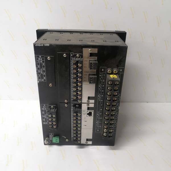
- Slot F I/O: 32 Digital Inputs (Option 4 board) + 0 Digital Outputs
- Slot G I/O: None (0)
- Total I/O Capacity: 32 Digital Inputs + 0 Digital Outputs
- Communication: Rear 10/100BaseTX Ethernet (COM3) + Front RS232/USB Port (COM2) + No rear serial ports
- Protocols: Modbus RTU/TCP, DNP 3.0 Level 2, IEC 60870-5-104, IEC 61850 Ed.2 (optional)
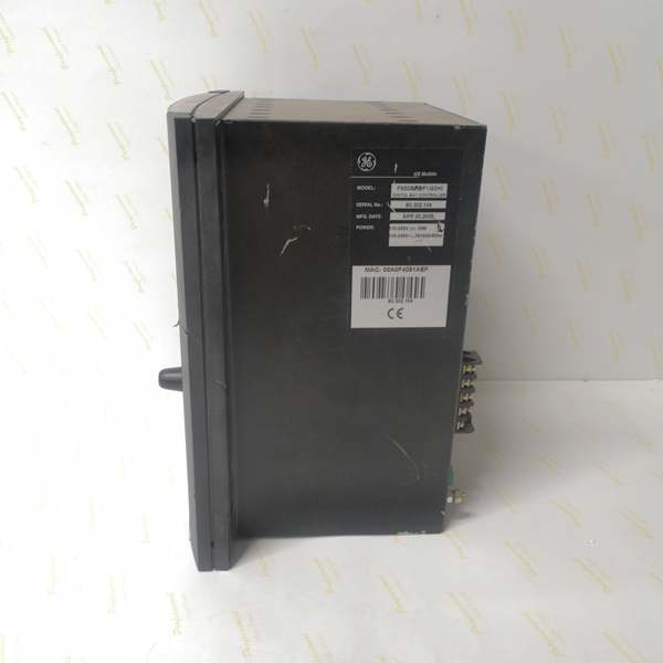
- Power Supply: 110-250V DC (88-300V range) / 120-230V AC (96-250V range), HI range
- Power Draw: 20-25 VA typical, 40 VA maximum
- Operating Temperature: -40°C to +70°C
- Isolation Rating: 2000V AC RMS I/O-to-chassis
- Dimensions: 168 × 150 × 55 mm (½ 19″ rack, 6U high)
- Weight: 5 kg (11 lbs)
- Language: English only (no C language code in order code)

The Real-World Problem It Solves
Complex bus schemes and multi-breaker installations generate massive amounts of status data—breaker position, disconnect status, ground switch position, isolator state. This 32-input configuration gives you a dedicated input matrix for comprehensive monitoring without sacrificing protection functionality or output capacity.
Where you’ll typically find it:
- Double-bus and transfer bus substations with extensive disconnect and breaker position monitoring
- Ring bus schemes requiring comprehensive switchgear status feedback
- Large industrial complexes with multiple motor starters, transformer taps, and interlock status points
- Distribution substations serving as monitoring hubs for surrounding equipment
This configuration focuses on status acquisition rather than control output, making it ideal for SCADA front-end applications where the relay acts as a status concentrator for downstream protection or control devices.
Hardware Architecture & Under-the-Hood Logic
This is a status-monitoring powerhouse. The Option 4 board in Slot F packs 32 digital inputs into a single module, communicating with the main CPU via CAN bus. With no outputs, the relay dedicates its processing power to input scanning, debouncing, and state monitoring.
- Main CPU Board: 32-bit RISC processor (>50 MIPS) with 32MB+ flash memory, executing protection algorithms while managing 32-input scanning via CAN bus
- DSP Module: Handles analog-to-digital conversion at 64 samples per power cycle for current/voltage inputs, independent of input board load
- Slot F I/O Board (Option 4): 32 digital inputs (24V DC programmable threshold) with individual debounce filtering, communicates via CAN bus to main CPU
- Slot G: Unpopulated—no I/O board installed
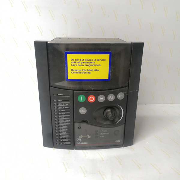
- Enhanced Display Module: 4×20 character alphanumeric LCD with front USB port supporting RS232/USB protocol
- Communication Module: 10/100BaseTX Ethernet controller on COM3, front RS232/USB on COM2, no rear serial ports
- Power Supply Module: Switching-mode power supply with >80% efficiency, lower VA draw due to zero output load
The 32 inputs are organized as four groups of eight inputs each, with individual debounce timers and programmable threshold detection (20-300V DC range for quasi-analog capability). Each input is optically isolated with 2000V AC RMS rating, and the CAN bus communication runs at 1Mbps to ensure state changes propagate within 10ms maximum. Since there are no outputs, the CPU loading is dominated by input scanning—critical protection inputs can be prioritized with faster debounce times while auxiliary status inputs use longer filtering.
Field Service Pitfalls: What Rookies Get Wrong
Input Debounce Overload32 inputs with improper debounce settings can saturate CPU loading. Rookies set all inputs to 50ms debounce “to be safe” and wonder why protection scan times degrade and event recording slows down.
Field Rule: Categorize your inputs. Critical protection inputs (breaker 52a/b, trip feedback) get 5-10ms debounce. Fast status signals (permissive signals, interlocks) get 10-20ms. Slow auxiliary signals (door position, fan status, temperature alarms) get 30-50ms. In EnerVista, monitor CPU loading—if it exceeds 70%, reduce debounce times on non-critical inputs. You don’t need 50ms debounce on a door position switch.
Quasi-Analog Input Configuration IgnoredThe Option 4 board supports programmable voltage thresholds (20-300V DC) for level detection. Techs treat all 32 inputs as simple dry contacts, missing the capability to detect specific voltage levels without external transducers.
Field Rule: If you need to detect specific DC voltage levels (24V, 48V, 125V), configure the input as “Quasi-Analog” in EnerVista with the appropriate threshold. This lets you detect voltage presence/absence without external relays or voltage transducers. Document which inputs are configured for threshold detection—future techs won’t expect 125V on a digital input terminal.
Wiring Density and Terminal Block Confusion32 inputs mean 64 wires (positive and negative for each input if using separate sources). Rookies don’t plan wire routing and end up with a mess of cables blocking ventilation and making troubleshooting impossible.
Field Rule: Plan your wire routing before pulling. Use color coding: red for positive, black for negative, blue for common returns. Group inputs by function (breaker status in one bundle, interlocks in another). Leave clearance between wire bundles and the relay ventilation slots. Use the bottom cable entry if your cabinet supports it. Document wire numbers in your test package—you’ll thank yourself during fault tracing.
No Outputs Means No Direct ControlTechs expect to find outputs like standard F650 models and are confused when there are none. This relay is a status monitor, not a control device.
Field Rule: If you need trip or control outputs, use the virtual outputs via IEC 61850 GOOSE messaging or Modbus TCP to downstream controllers. This relay is designed to concentrate status information and communicate it, not to directly trip breakers. If you need local tripping, specify an F650 with Slot F Option 1 or 2 instead. Don’t try to hack control functionality into a 32-input-only relay.
CAN Bus Loading with Rapid State Changes32 inputs changing state rapidly (during switching operations or fault clearing) can flood the CAN bus with state change messages. Rookies see occasional missed state updates and blame the relay.
Field Rule: Configure input state change reporting appropriately. Not every input needs immediate transmission on every change. Use reporting delays for non-critical status inputs (20-50ms) while keeping critical inputs at immediate reporting. In EnerVista, set “Event Reporting” to filter unnecessary chatter. This reduces CAN bus loading without compromising protection-critical information.
Ground Loop Susceptibility with 32 Inputs32 opto-isolated inputs mean 32 isolation barriers. If the input sources have different ground references, ground loops can cause erratic behavior or false readings.
Field Rule: Verify all input sources share a common reference or are properly isolated. Use separate isolated DC supplies for different input groups if needed. Measure potential difference between input commons before wiring—anything above 5V AC indicates a ground loop problem. Document grounding architecture in your commissioning package. When in doubt, use signal isolators on suspicious inputs.
Firmware Upgrade via USB StabilityWith 32 inputs potentially active during operation, firmware upgrades can be interrupted if input state changes trigger watchdog resets during the upload process.
Field Rule: Before firmware upload: disable non-essential inputs or put the system in a safe state with minimal activity. Use only GE0100-0001 USB cable. Verify stable AC/DC power. Close EnerVista on all other PCs. Never interrupt the upload—if it hangs, wait 15 minutes before power cycling. The bootloader has recovery routines that need time to complete, especially with active I/O boards.
Commercial Availability & Pricing NotePlease note: The listed price is for reference only and is not binding. Final pricing and terms are subject to negotiation based on current market conditions and availability.


