
Description
Hard-Numbers: Technical Specifications
- Protection Elements: 50/51 (phase overcurrent), 50N/51N (neutral), 50G/51G (ground), 67 (directional), 21 (distance), 79 (4-shot autorecloser), 50BF (breaker failure), 27/59 (undervoltage/overvoltage), 81U/O (under/over frequency), 81R (ROCOF), 49 (thermal)
- Analog Inputs: 3-phase CT (1A/5A configurable, range 0.1-6000A), 3-phase VT (up to 208V L-N)
- Digital Inputs: Up to 80 inputs (8 standard in Slot F, expandable via CIO modules)
- Digital Outputs: Up to 56 outputs (8 standard in Slot F, Form-A/Form-C/Form-SSR available)
- Communication Protocols: IEC 61850 Ed.2 (MMS, GOOSE, SV), IEC 60870-5-103/104, DNP3.0 (serial/TCP), Modbus RTU/TCP, IEEE 1588 PTP, IRIG-B, SNTP
- Ethernet Ports: 1× 10/100BaseTX (rear board B), optional 100 Base FX fiber module available in other variants
- Serial Ports: 2× RS485 (rear board A, redundant), 1× RS232 front panel
- Operating Temperature: -25°C to +70°C (conformal coating variant)
- Isolation Rating: 2000V AC RMS I/O-to-chassis, 1500V RMS channel-to-channel
- Power Input: 48-250V DC (expanded range) or 100-240V AC (expanded range)
- Power Draw: 30W maximum
- Environmental Protection: Conformal coating on PCBs for harsh chemical/salt-mist environments
- Oscillography: Up to 512 records, programmable sampling (64 samples/cycle max), up to 5 seconds capture
- Event Recorder: 479-512 events, 1ms time-tag resolution
- Trip Time: ≤20ms typical for instantaneous overcurrent
- Language Support: English-only (no Chinese language option)

The Real-World Problem It Solves
Industrial substations in harsh environments face corrosion from salt mist (coastal), sulfur compounds (refineries), and chemical vapors (chemical plants). Standard relays with bare PCBs develop dendritic growth, leading to intermittent faults and premature failure. The F650BABF2G0I with conformal coating (“0” suffix) provides a protective barrier on all internal circuit boards, extending MTBF in corrosive atmospheres. When combined with the F650’s consolidated protection (overcurrent, distance, breaker failure), it reduces panel footprint and eliminates the need for separate corrosion-resistant enclosures for multiple legacy relays. The “0” code in Slot G indicates no expansion module is installed—simplified configuration for applications with limited I/O requirements.
Where you’ll typically find it:
- Coastal substations exposed to salt-mist corrosion
- Petrochemical plants with sulfur-rich atmospheres
- Offshore wind farm collection substations
- Industrial facilities with aggressive chemical environments (chlorine, ammonia, acidic vapors)
- Mining sites with high humidity and particulate contamination
Bottom line: Conformal coating protects the relay’s internals from corrosion where standard models would fail. English-only interface and no expansion slot keeps it simple for applications where harsh environment protection outweighs high I/O count requirements.
Hardware Architecture & Under-the-Hood Logic
This is the same modular microprocessor-based architecture as other F650 variants, but with a critical difference: all PCBs (CPU, I/O, communications, power supply) have conformal coating—a thin polymer film that seals the board against moisture, chemicals, and conductive contaminants. The CPU handles protection algorithms, programmable logic, and communications via CAN bus backplane. No FPGA—all processing runs on 32-bit CPU with deterministic scan cycles. The “F2” code in Slot F means 8 digital inputs + 8 outputs + 2 trip/close supervision circuits. The “G0” code indicates Slot G is empty (no expansion board). The “I” suffix denotes harsh environment protection with conformal coating.
- CT/VT modules isolate and digitize analog inputs (current/voltage from field transformers)
- Digitized samples stream to CPU via internal CAN bus at up to 64 samples/cycle
- CPU executes protection element algorithms (overcurrent, distance, directional) in real-time
- Programmable logic engine processes inputs from protection elements, digital contacts, and remote GOOSE messages
- Trip/control decisions routed to output relay modules with <2ms contact response time
- Oscillography engine captures pre-fault (up to 5 cycles) and post-fault data to non-volatile memory
- Communication modules push GOOSE/IEC 61850 messages to upstream SCADA via Ethernet ports
- Breaker failure element monitors fault current after trip initiation—if current persists beyond setpoint, triggers backup trip output
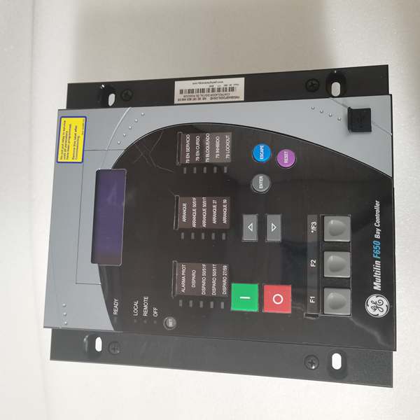
- Basic LCD display renders English-only screens for local monitoring and parameter configuration
- Critical difference: All PCB assemblies are coated with transparent conformal coating material, providing corrosion resistance in harsh environments
Field Service Pitfalls: What Rookies Get Wrong
Damaging Conformal Coating During RepairThe conformal coating is a protective polymer film—rookies scratch or scrape it off when probing test points or replacing components. Once the coating is breached, corrosion can penetrate the PCB. In coastal environments, uncoated traces corrode within months, causing intermittent faults that are nearly impossible to diagnose.
- Field Rule: Never scrape or remove conformal coating unless absolutely necessary. If you must probe a test point, use a fine needle to gently pierce the coating rather than scraping. After any repair, reapply conformal coating material (acrylic, urethane, or silicone, matching the original) to seal the exposed area. Verify coating integrity visually—no bare copper or solder joints should be exposed.
Grounding Without Coating ConsiderationStandard practice is to connect relay chassis ground to substation ground grid. Rookies use standard lugs with sharp teeth that dig into the relay’s paint. In corrosive environments, the ground connection corrodes at the paint penetration point, creating high-resistance paths. The relay loses effective ground, making it vulnerable to surges and EMI.
- Quick Fix: Use star washers with proper torque specs to bite through paint and conformal coating at designated ground points, ensuring metal-to-metal contact. After tightening, apply corrosion-inhibiting grease to the connection. Verify ground continuity with a milliohm meter—should read <10mΩ. Periodic inspection (annual) is required in coastal areas to prevent ground degradation.
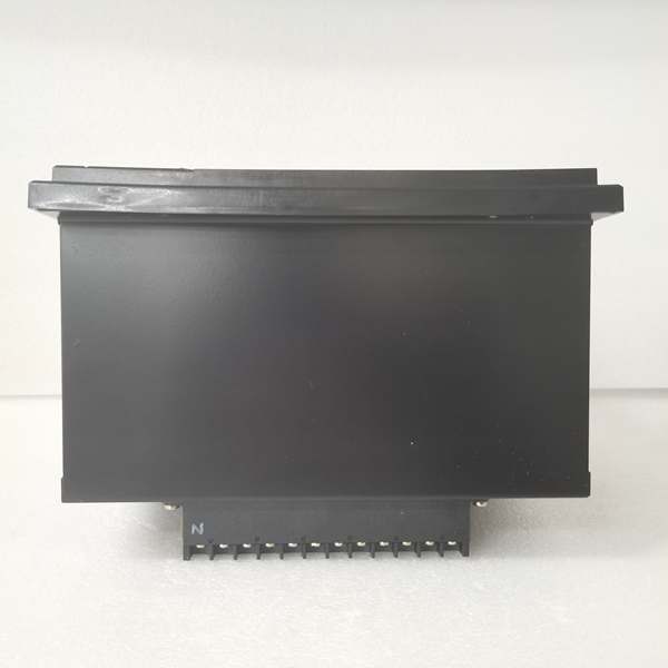
Missed Power Input Range DifferencesThe conformal coating variant (F650BABF2G0I) has expanded power input range: 48-250V DC / 100-240V AC. Rookies wire it assuming the standard 110-250V DC / 120-230V AC range and reject it for 48V DC sites, unnecessarily ordering replacement relays. This model can actually operate from 48V DC, making it suitable for telecommunication-battery-backed substations.
- Field Rule: Always verify the full power input range on the label or datasheet before rejecting a relay. The conformal coating variant supports 48V DC (minimum 48V, not 24V). If the substation has 48V DC battery backup, this relay can run directly from it without an additional DC-DC converter. Confirm power source compatibility during commissioning—check the rear label for “48-250V DC” specification.
Conformal Coating Masking Diagnostic LEDsSome conformal coating applications overspray and partially cover front-panel LEDs or display segments. Rookies assume the relay is faulty when LEDs appear dim or the display flickers, and replace the unit unnecessarily. The coating itself is causing the optical distortion, not an electrical fault.
- Quick Fix: Visually inspect the front panel under bright light—if a thin film is visible over LEDs or display, use a soft cloth with isopropyl alcohol to gently clean the affected areas. Do not scrape. If the coating has penetrated the LED light guides (rare), contact GE support for RMA. Most cases are simply surface contamination that cleans off, restoring full brightness.
Moisture Condensation on Cold Relays in Warm Humid SitesIn coastal substations with wide temperature swings, the relay can get cold at night and accumulate condensation in the morning. Even with conformal coating, water can pool on connectors or under the bezel. Rookies assume conformal coating makes the relay waterproof—they don’t seal panel gaskets, leading to water ingress at the rear terminals.
- Field Rule: Conformal coating protects the PCBs, not the relay’s connectors or enclosure. Always use proper panel gaskets and seal conduit entries with silicone or IP-rated cable glands. In high-humidity coastal areas, consider installing a small heater in the relay cabinet to maintain temperature above dew point. Monitor humidity—if cabinet humidity exceeds 85% RH, install desiccant or active dehumidification.
Extended Warm-Up Time in Cold Corrosive EnvironmentsIn offshore platforms or northern coastal sites, the relay can start at -10°C or lower. The conformal coating material becomes more rigid at low temperatures, slightly affecting thermal dissipation. Rookies assume the relay is faulty when it takes 30-60 seconds to fully boot and display values, compared to 10 seconds in temperate environments.
- Quick Fix: Allow extended warm-up time for conformal-coated relays in cold environments—up to 90 seconds is normal below 0°C. If the relay fails to boot after 2 minutes, check power input voltage and verify the heater circuit (if installed) is working. Do not cycle power repeatedly—this can cause thermal stress on the coating. Cold-start performance is within specification for conformal-coated variants.
Commercial Availability & Pricing Note
Please note: The listed price is for reference only and is not binding. Final pricing and terms are subject to negotiation based on current market conditions and availability.


