
Description
Hard-Numbers: Technical Specifications
- Input Channels: 16 digital inputs (125V DC opto-isolated)
- Output Channels: 16 digital outputs (125V DC, 2A each)
- Logic Elements: 64 configurable AND/OR gates, 8 timers
- Timer Range: 0.1-999.9 seconds (configurable)
- Response Time: <10ms input-to-output
- Isolation: 1500V AC (input to logic, logic to output)
- Operating Temp: -40°C to +70°C
- Terminal Blocks: 4 blocks × 8 terminals each
- LED Indicators: Power (green), Input Status (16× yellow), Output Status (16× green), Fault (red)
- Power Draw: 600mA @ 125V DC
- Weight: 1.3 kg (2.9 lbs)
- Mounting: Backplane via edge connector
- Compatible Controllers: Mark IV, Mark IV Speedtronic
- Revision: 1D1B (enhanced timer precision, conformal coating)

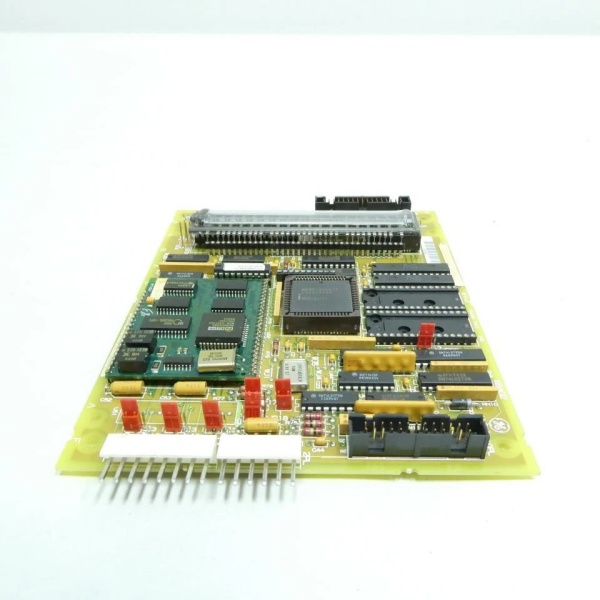
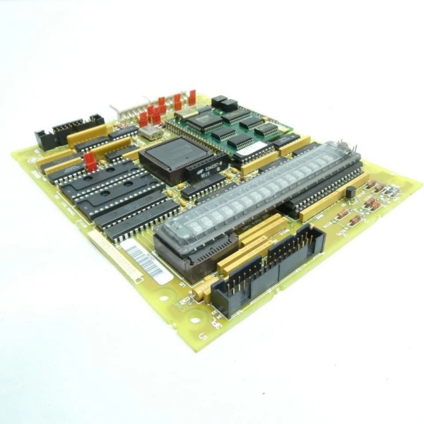
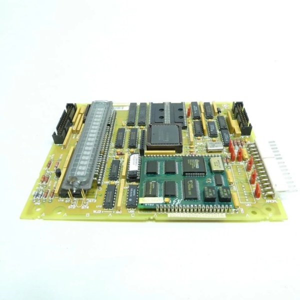
GE DS200SLCCG3ACC
The Real-World Problem It Solves
Turbine control systems need more than simple on/off logic—they need AND/OR combinations, interlock sequencing, and time delays. Loading all that logic into the main processor bogs it down and creates a single point of failure. This board handles dedicated logic functions locally, keeping the main controller free for higher-level control while providing faster response times.
Where you’ll typically find it:
- Mark IV turbine control racks executing valve interlock logic
- Steam turbine startup/shutdown sequencing control
- Gas turbine purge and fire protection logic
- Emergency shutdown system interlock processing
Bottom line: Dedicated logic processing with timer functions offloads the main controller and speeds up critical interlock response.
Hardware Architecture & Under-the-Hood Logic
This is a configurable logic board with discrete gate logic and timer circuits. No microprocessor—all logic functions are hardwired via FPGA-like matrix or discrete logic gates that you configure through jumper settings or EEPROM programming. The 1D1B revision adds improved timer accuracy.
- Digital inputs enter through opto-isolated terminal blocks
- Input conditioning circuits convert 125V DC to 5V logic levels
- Configurable logic matrix processes AND/OR combinations
- Timer circuits provide on-delay, off-delay, and pulse functions
- Logic results feed to output driver circuits
- Output drivers energize relay coils or indicator loads
- Optoisolators separate output stage from logic section
- Fault detection circuit monitors logic matrix health
- Status LEDs reflect real-time input/output states
- Conformal coating (1D1B) protects against humidity and corrosion
GE DS200SLCCG3ACC
Field Service Pitfalls: What Rookies Get Wrong
Configuring Logic Without Documenting Jumper SettingsSetting up an interlock sequence and moving jumpers around to make it work. Six months later, the board fails, and nobody knows how it was configured. The replacement board doesn’t behave the same, and you’re dead in the water.
- Field Rule: Document every jumper position and logic configuration before making changes. Photograph the board if necessary. Store the configuration with the site documentation—when a board fails, you need to know exactly how to configure the replacement.
Timer Drift After Five YearsThe board was installed in 2019 with a 30-second startup delay timer. Now it’s 2026, and the timer runs 35 seconds. The tech recalibrates, but it drifts again after a thermal cycle. The RC timing components are aging and can’t hold stable anymore.
- Quick Fix: If timer drift exceeds 5% of the set value, the timing capacitor is degrading. Recalibration is temporary—replace the board or the timing module. For critical timing functions, consider moving the timer function to the main controller, which has stable crystal-based timing.
Loading Outputs Beyond 2A RatingConnecting a 5A solenoid directly to the output terminal because “the interlock board said to fire it.” The output transistor overheats and fails after 50 cycles. Now the interlock never completes, and the turbine won’t start.
- Field Rule: Board outputs are rated 2A maximum. For loads above 2A, use the board output to drive an intermediate relay or contactor. Never exceed the output rating—welded contacts or blown transistors cause dangerous uncontrolled operation.
Mixing AC and DC on Digital OutputsWiring a 120V AC indicator lamp to a 125V DC output terminal. The AC reverses polarity every cycle, and the output protection diodes conduct, heating up the output stage. Within minutes, the output is destroyed.
- Field Rule: Verify load type before wiring. These are DC-only outputs—125V DC nominal. If you need to switch AC loads, use an external relay or contactor. The optoisolators and output transistors are not designed for AC switching.
Commercial Availability & Pricing Note
Please note: The listed price is for reference only and is not binding. Final pricing and terms are subject to negotiation based on current market conditions and availability.


