
Description
Hard-Numbers: Technical Specifications
- Input Channels: 16 single-ended analog inputs
- Input Types: 4-20mA, 0-10V DC, 0-5V DC (configurable)
- Isolation: 500V AC channel-to-ground
- Input Range: 0-20mA (current mode), 0-10V (voltage mode)
- ADC Resolution: 12-bit successive approximation
- Sampling Rate: 50 samples per second per channel
- Operating Temp: -40°C to +70°C
- Terminal Blocks: 8 blocks × 4 terminals each
- LED Indicators: Power (green), Channel Active (16× yellow)
- Power Draw: 750mA @ 125V DC
- Weight: 1.1 kg (2.4 lbs)
- Mounting: Backplane via edge connector
- Compatible Controllers: Mark IV, Mark IV Speedtronic
- Revision: C1E1 (enhanced linear accuracy, improved drift compensation)

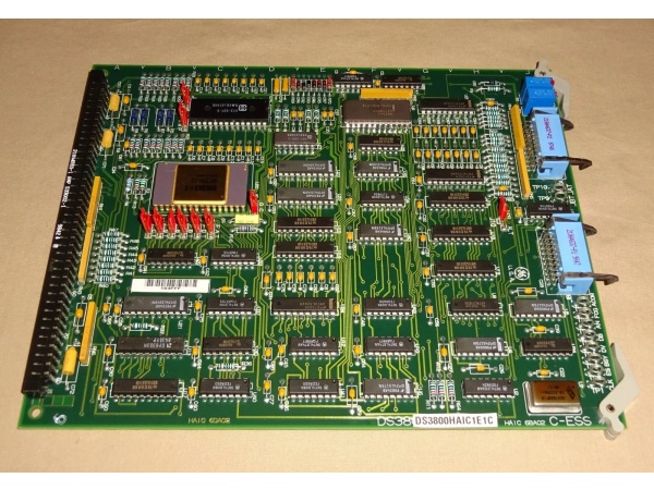
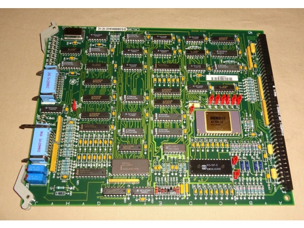
DS3800HAIC1E1
The Real-World Problem It Solves
Not every field sensor outputs millivolt-level signals. Modern transmitters send clean 4-20mA or 0-10V signals from the field, and you don’t need differential isolation for every channel. This board gives you 16 single-ended inputs optimized for high-level signals, letting you handle more transmitters per board without the cost and complexity of full differential isolation.
Where you’ll typically find it:
- Mark IV turbine control racks processing 4-20mA transmitter signals
- Steam and gas turbine valve position feedback loops
- Hydraulic and lube oil pressure transmitter arrays
- Generator excitation current and voltage monitoring
Bottom line: 16 channels of high-level analog conditioning in one board—perfect for the 4-20mA world of modern transmitter instrumentation.
Hardware Architecture & Under-the-Hood Logic
This is a single-ended analog input board with multiplexed conversion and software-configurable input ranges. Each channel has basic overvoltage protection and current shunt resistors for mA-mode operation. No onboard processor—all scaling and linearization happens in the main controller.
- Analog signal enters through terminal block
- Input protection circuit (TVS diodes, PTC fuse) clamps surges
- Range selection circuitry routes signal to appropriate conditioning path
- Current mode: signal passes through 250Ω precision shunt resistor
- Voltage mode: signal passes through voltage divider/attenuator
- Analog multiplexer routes selected channel to ADC
- 12-bit successive approximation ADC converts to digital value
- Digital data transmitted across backplane via parallel bus
- Channel active LEDs indicate which channels are scanning
- Software-configurable ranges allow per-channel type selection
DS3800HAIC1E1
Field Service Pitfalls: What Rookies Get Wrong
Mixing 4-20mA and 0-10V Inputs on the Same BoardSetting all channels to current mode in software, then wiring a 0-10V position transmitter to channel 8. The transmitter sees a 250Ω load and tries to drive 40mA—way beyond its spec. Output clips at 8V, and the valve position reads 80% when it’s actually 100%.
- Field Rule: Verify software channel configuration matches the wired device type. Never assume “all 4-20mA” is the default. Each channel is independently configurable—double-check the config before applying field voltage.
Missing Return Wire on Current InputsWiring a 2-wire 4-20mA transmitter with only the positive lead connected. The current has no return path to the board’s shunt resistor, so the board reads zero. Tech adds a ground wire, creating a ground loop through the transmitter case.
- Quick Fix: 2-wire transmitters need both positive and negative connections to the board. The board provides the loop power—don’t connect the transmitter negative to ground. Use the dedicated RTN (return) terminal for each current input.
Overloading the Board Power SupplyFilling all 16 channels with 4-20mA transmitters and adding an extra 8-channel board to the same power bus. The combined load exceeds the 125V DC supply capacity, causing brownouts that reset the entire rack.
- Field Rule: Calculate total power draw before populating all channels. Each 4-20mA input draws loop power from the board’s supply. At full scale (16 channels × 20mA), you’re pulling 320mA just for the transmitters—add that to the board’s 750mA base draw. Verify your supply can handle it.
Zero Span Drift After Temperature CyclingThe board ran for five years in a 50°C cabinet. Now channels 3-5 read 2% high at zero input. Tech recalibrates, but the drift comes back after the next thermal cycle. The reference voltage diode is aging and can’t hold stable anymore.
- Field Rule: If zero/span drift is temperature-dependent, the onboard reference is failing. Recalibration is a temporary fix. Replace the board or the reference voltage module—once drift exceeds 0.5% after warmup, the board is at end-of-life.
Commercial Availability & Pricing Note
Please note: The listed price is for reference only and is not binding. Final pricing and terms are subject to negotiation based on current market conditions and availability.


