
Description
Hard-Numbers: Technical Specifications
- Input Channels: 8 differential analog inputs
- Input Types: mV (TC), Ω (RTD), mA (4-20), V (0-10)
- Isolation: 1500V AC channel-to-channel, 2500V AC channel-to-ground
- Input Range: ±50mV to ±10V (software configurable)
- ADC Resolution: 16-bit successive approximation
- Sampling Rate: 100 samples per second per channel
- Operating Temp: -40°C to +70°C
- Terminal Blocks: 4 blocks × 8 terminals each
- LED Indicators: Power (green), Channel Fault (8× red)
- Power Draw: 500mA @ 125V DC
- Weight: 0.95 kg (2.1 lbs)
- Mounting: Backplane via edge connector
- Compatible Controllers: Mark IV, Mark IV Speedtronic
- Revision: 1C1C (enhanced EMI protection, conformal coating)

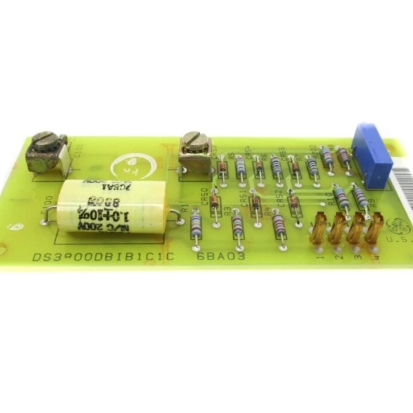
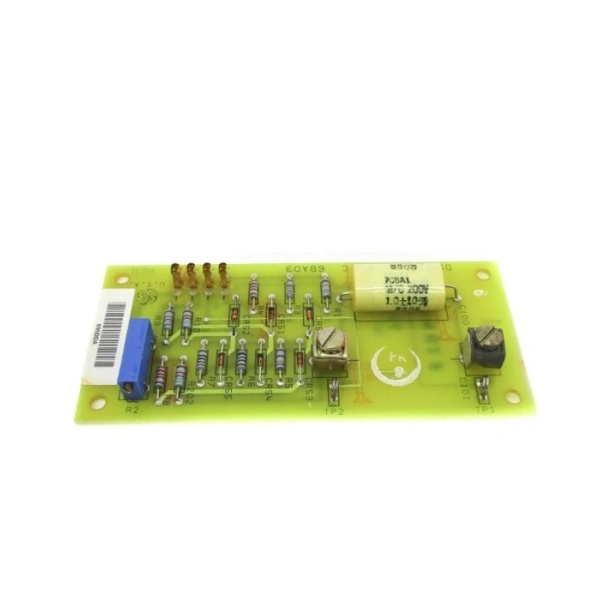
GE DS3800DBIB1C1C
The Real-World Problem It Solves
The base DBIB board handled differential signals well, but in environments with extreme EMI—like cabinets sitting next to 4160V motor feeders or VFD output buses—noise still leaked through. The 1C1C revision adds enhanced filtering and better shielding, killing residual noise that caused false alarms on temperature and pressure channels.
Where you’ll typically find it:
- Mark IV turbine control racks in high-EMI environments
- Steel mill turbine cabinets near large DC drives
- Combined-cycle plants with extensive variable-frequency drive installations
- Gas turbine control systems requiring tight temperature tolerance
Bottom line: Same differential isolation as the standard DBIB, with extra noise suppression for the really ugly electrical environments.
Hardware Architecture & Under-the-Hood Logic
Same core architecture as the base DBIB—8 isolated differential channels feeding a multiplexed 16-bit ADC. The 1C1C revision adds pi-network filtering on each input and upgraded optoisolators with higher CMRR. The “1C1C” suffix also indicates conformal coating for harsh environments.
- Differential signal enters through isolated input terminal block
- Enhanced pi-network filter (LC) provides additional EMI rejection
- Input protection circuit (TVS diodes, current limiting) clamps surges
- Instrumentation amplifier provides high CMRR differential amplification
- Upgraded optoisolators create galvanic isolation barrier per channel
- Analog multiplexer routes selected channel to ADC
- 16-bit successive approximation ADC converts to digital value
- Digital data transmitted across backplane via parallel bus
- Fault detection circuit monitors input open/short conditions
- Channel fault LEDs indicate per-channel health status
- Conformal coating (1C1C) protects against humidity and corrosion
GE DS3800DBIB1C1C
Field Service Pitfalls: What Rookies Get Wrong
Replacing 1C1C with Standard DBIBDropping in a non-1C1C DBIB as a replacement “because that’s all we had.” The enhanced filtering is gone, and suddenly channels 4-6 start oscillating 5°C when the nearby VFD ramps up. Plant trips, and you can’t figure out why.
- Field Rule: Never downgrade a 1C1C board to a standard DBIB in high-EMI locations. If 1C1C is unavailable, add external filtering to the field inputs or relocate the cabinet. Document the downgrade and monitor for noise issues.
Mismatched Software ConfigurationLoading standard DBIB calibration values into the controller for a 1C1C board. The enhanced filter introduces a 2ms phase delay, and the controller timing is now off. Temperature readings lag real conditions by 200ms.
- Quick Fix: Always verify software configuration matches the installed board revision. 1C1C boards require specific filter delay parameters in the controller configuration. If values aren’t available, perform a full calibration cycle with the new board installed.
Damaging Conformal Coating During Terminal WorkUsing a screwdriver to pry off terminal blocks and scraping through the conformal coating. Once breached, humidity creeps under the coating and corrosion spreads to the isolation barriers. Six months later, the board starts reading ghost voltages.
- Field Rule: Use plastic tools when working around conformal-coated boards. If the coating is damaged, clean the area with isopropyl alcohol and reapply conformal coating spray before reinstallation. Never leave exposed copper traces unprotected.
Forgetting the 1C1C Has Different Input ImpedanceThe 1C1C revision has 500kΩ input impedance instead of 250kΩ on the standard board. Connecting a transmitter expecting 250kΩ load causes the output to run slightly low. Readings are off by 1-2%, and you chase calibration ghosts.
- Field Rule: Verify input impedance specifications when swapping board revisions. The 1C1C has 500kΩ input—recalibrate transmitter outputs or adjust scaling factors in the controller configuration to compensate for the impedance difference.
Commercial Availability & Pricing Note
Please note: The listed price is for reference only and is not binding. Final pricing and terms are subject to negotiation based on current market conditions and availability.


