
Description
Hard-Numbers: Technical Specifications
- Functional Acronym: DACA (Digital Analog Converter Assembly)
- Input Voltage: 115 V AC / 230 V AC (50/60 Hz)
- Output Voltage: 125 V DC (nominal 107 V DC)
- Output Power Rating: 1000 W
- Maximum Output Current (Single Module): 9.5 A DC
- Maximum Output Current (Parallel): 16.5 A DC (derated)
- Efficiency: 95% typical
- Power Distribution: 125 V DC bus creation via diode coupling
- Cooling Method: Free convection (air-cooled, no fans)
- Operating Temperature: -22°F to +140°F (-30°C to +60°C)
- Humidity Range: 5% to 95% non-condensing
- Life Expectancy: 100 years at 68°F (20°C)
- Connector: Single 12-position connector (JZ) for AC input and DC output
- Capacitor Type: Replaceable electrolytic capacitors
- Grounded Voltages: +62.5 V and -62.5 V (when diodes coupled and center grounded)
- Replacement Cycle: Every 5 years at 149°F (65°C) ambient
- Backward Compatibility: Replaces DS2020DACAG1 (drop-in replacement)
- Parallel Support: Yes, requires same AC source for all modules
- Weight: 48.39 lbs (21.95 kg)
- Dimensions: 28 cm × 11.5 cm × 4.5 cm
- Manuals: GEH-6632 (EX2100), GEH-6721G (Mark VIe), GEH-6721L (PDM)
- Compliance: RoHS compliant

GE DS2020DACAG2
The Real-World Problem It Solves
Excitation control systems require stable 125V DC power to operate controller modules, gate pulse amplifiers, and protection circuits. The DS2020DACAG2 (DACA Power Conversion Module) solves the problem of converting available 115V or 230V AC utility power into regulated 125V DC with built-in energy storage for ride-through during power interruptions. Without this conversion, excitation systems would need external battery banks or DC power supplies, adding complexity and maintenance requirements. The module’s 1000W output capacity provides sufficient power for EX2100 excitation control systems, while the ability to parallel two modules increases maximum output current to 16.5A derated for high-demand applications. The replaceable electrolytic capacitors provide local energy storage, extending ride-through time during control power loss—when AC input fails, the capacitors discharge to maintain DC output long enough for orderly shutdown or transfer to backup power. The DS2020DACAG2 is a drop-in replacement for the earlier DS2020DACAG1 with virtually no functional differences, offering backward compatibility while supporting parallel operation—a capability the earlier model did not recommend. The module’s wide temperature range (-22°F to +140°F) and free convection cooling allow installation in various environments without forced air cooling, reducing maintenance requirements. Power conversion at 95% efficiency minimizes heat generation and energy waste, making it suitable for continuous operation in power generation facilities. The diode-coupled output creates a DC bus that feeds all controller modules and gate pulse amplifier boards, with LED indicators on connected boards (EPDM, EGPA, EXTV, EPBP) confirming proper power supply status.
Where you’ll typically find it:
- EX2100 excitation control systems in generator and motor applications
- Mark VIe turbine control cabinets with 125V DC power requirements
- Power distribution modules (PDM) requiring AC/DC conversion
- Industrial applications with 125V DC bus requirements
- Sites operating without battery backup, relying on local energy storage
Bottom line: High-efficiency AC/DC power converter with parallel capability and replaceable capacitors—provides 125V DC power with ride-through capability, replacing DS2020DACAG1 while supporting redundant configurations for critical excitation control systems.
Hardware Architecture & Under-the-Hood Logic
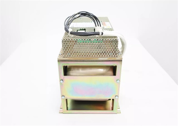
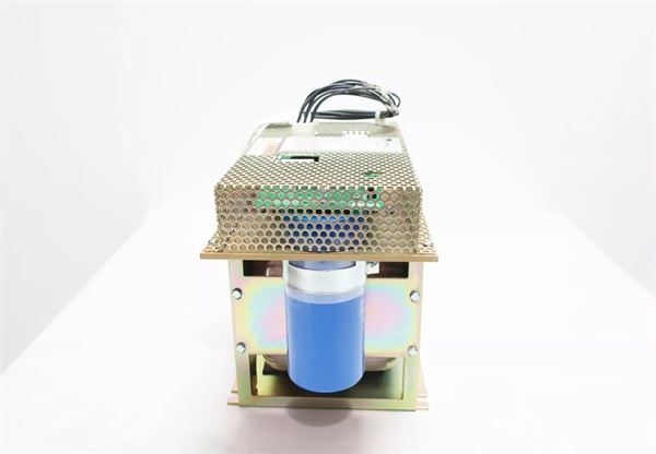
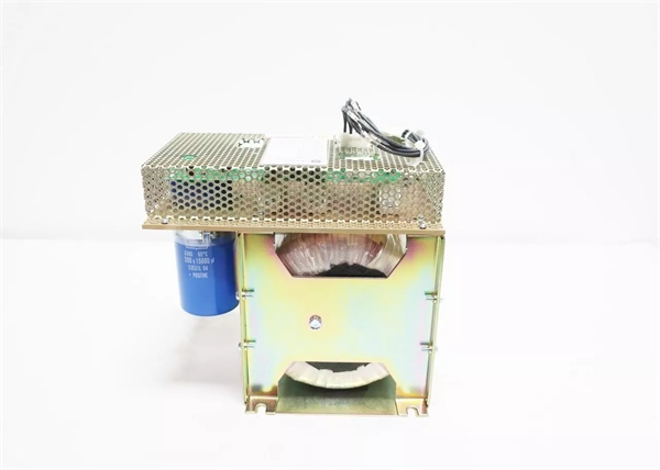
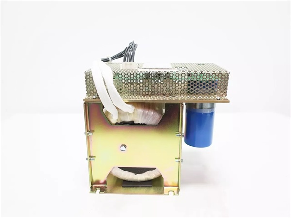
The DS2020DACAG2 is an AC/DC power conversion assembly built around a full-wave bridge rectifier, output filter capacitor bank, and voltage regulation circuitry that converts AC input to regulated 125V DC output. The module receives AC power through the 12-position JZ connector, supporting either 115V or 230V AC input at 50/60Hz frequency—input voltage selection is typically handled by internal wiring or jumpers (115V uses connector JTX1, 230V uses JTX2 in related designs). The AC input passes through an input filter to attenuate harmonic currents and reduce electromagnetic interference before reaching the full-wave bridge rectifier. The bridge rectifier converts the AC sine wave to pulsating DC, which the large electrolytic capacitor bank smoothes into a relatively steady DC voltage with minimal ripple. This raw DC passes through voltage regulation circuitry that maintains stable 125V DC output regardless of input voltage variations within the specified range or output load changes. The regulated output connects to the DC bus through isolation diodes that allow paralleling with other DC sources—the diodes prevent back-feeding between power sources while enabling load sharing. When diodes are coupled and the system center ground is established, the 125V DC bus splits into +62.5V and -62.5V referenced to ground, providing balanced bipolar voltage for sensitive control circuits. The electrolytic capacitor bank serves dual purposes: filtering the rectified DC output to reduce ripple and providing energy storage for ride-through during AC power loss. Capacitor capacity determines ride-through time—larger capacitance extends the time the module can supply power after input failure. These electrolytic capacitors are the wear-out components, with lifespan heavily dependent on ambient temperature—at 68°F (20°C), they’re rated for 100-year life, but at 149°F (65°C), replacement is required every 5 years. The module supports parallel operation with another DS2020DACAG2 unit to increase total output capacity to 16.5A DC maximum, but both modules must connect to the same AC source to ensure equal input voltages and proper load sharing—parallel modules with different AC sources would cause circulating currents and uneven loading. Protection circuits monitor for overcurrent, overvoltage, and short-circuit conditions, disconnecting the output if faults occur and preventing damage to the module or connected equipment. LED indicators on the module and connected boards (EPDM, EGPA, EXTV, EPBP) provide status indication—green LEDs confirm proper power supply, while fault indicators trigger on overvoltage, undervoltage, or overcurrent conditions. The module operates with free convection cooling—no fans or forced airflow required—relying on the metal mesh housing for heat dissipation, which simplifies maintenance and eliminates fan failure points.
Signal flow:
- AC input power received via 12-position JZ connector (115V or 230V)
- Input filter attenuates harmonic currents and reduces EMI
- Full-wave bridge rectifier converts AC to pulsating DC
- Electrolytic capacitor bank smoothes pulsating DC to steady DC
- Capacitor bank provides energy storage for ride-through during power loss
- Voltage regulation circuitry maintains stable 125V DC output
- Regulated output passes through isolation diode for bus coupling
- Diode couples with other DC sources to create DC bus
- DC bus distributes power to controller modules and gate pulse amplifiers
- Output boards (EPDM, EGPA, EXTV, EPBP) receive 125V DC power
- LED indicators on connected boards confirm power supply status
- Protection circuits monitor for overcurrent, overvoltage, short circuits
- Fault conditions trigger protection disconnect and fault alerts
- Capacitor discharge provides ride-through during AC power interruption
- Parallel modules share load via isolation diodes (if configured)
- Heat dissipated via free convection through metal mesh housing

GE DS2020DACAG2
Field Service Pitfalls: What Rookies Get Wrong
Connecting parallel modules to different AC sourcesParalleling DACA modules from separate AC feeds. I’ve seen technicians connecting two modules to different phases or even different transformers, causing circulating currents, uneven loading, and overheating.
- Field Rule: All parallel modules must connect to the same AC source with identical voltage and phase. Verify AC input voltage is identical across all modules before paralleling. Different sources cause current imbalances and can damage modules.
Not waiting for capacitor discharge before handlingTouching internal components immediately after power removal. I’ve seen technicians receiving shocks from charged capacitors because they rushed disassembly without allowing adequate discharge time.
- Field Rule: Wait at least 1 minute after power removal before handling the module. Verify zero voltage on capacitor terminals with a multimeter before touching any components. The capacitor bank stores lethal voltage—respect the discharge time.
Mixing 115V and 230V input configurationsInstalling modules with incorrect input voltage settings. I’ve seen technicians wiring 230V modules into 115V systems or vice versa, causing output voltage issues or component stress.
- Field Rule: Verify input voltage configuration matches the available AC supply before installation. Check internal wiring and jumper settings—115V and 230V configurations are not interchangeable. Wrong input voltage causes unstable operation or premature failure.
Neglecting capacitor replacement in high-temperature environmentsRunning modules past 5-year replacement cycle at elevated temperatures. I’ve seen technicians ignoring the capacitor wear-out schedule in hot locations, then experiencing output voltage ripple and module failure.
- Field Rule: Replace modules every 5 years when ambient temperature is 149°F (65°C). Capacitor life is temperature-dependent—higher temperatures accelerate aging. Track installation dates and schedule proactive replacements in hot environments.
Overloading parallel modules beyond derated currentExpecting full 19A output from two parallel modules. I’ve seen technicians assuming parallel operation doubles output capacity linearly, drawing 19A total and tripping protection circuits.
- Field Rule: Parallel operation maximum is 16.5A DC derated, not 19A. Account for current sharing derating between modules. Don’t assume linear scaling—derating accommodates voltage and impedance variations between modules.
Forgetting to verify output voltage after replacementAssuming output is correct without measurement. I’ve seen technicians replacing modules and immediately returning the system to service without verifying the 125V DC output is within specification.
- Field Rule: Always measure output voltage after replacement. Verify 125V DC nominal output is within tolerance before commissioning. Confirm +62.5V and -62.5V ground-referenced voltages if the system uses center ground configuration.
Improper grounding of the module chassisLeaving the module chassis ungrounded during installation. I’ve seen technicians mounting modules without grounding the chassis, creating shock hazards and potential ground fault issues.
- Field Rule: Module chassis must be grounded to the cabinet ground. Verify ground connection integrity before applying power. Ungrounded modules pose shock hazards and can cause erratic operation.
Blocking airflow to metal mesh housingInstalling modules with obstructed ventilation. I’ve seen technicians mounting modules against cabinet walls or stacking equipment, blocking free convection cooling and causing overheating.
- Field Rule: Maintain clearance around the metal mesh housing for airflow. Free convection requires unobstructed ventilation—don’t block the front or rear. Ensure adequate spacing from other heat-generating equipment.
Ignoring ripple measurements during maintenanceAssuming capacitor health without testing. I’ve seen technicians skipping ripple voltage measurements during annual maintenance, missing early signs of capacitor degradation before failure occurs.
- Field Rule: Measure output ripple voltage annually with an oscilloscope. Increasing ripple indicates capacitor degradation—replace modules before ripple causes issues. Don’t wait for complete failure—monitor ripple trends to predict maintenance needs.
Mixing old and new modules in parallel configurationsCombining DS2020DACAG1 and DS2020DACAG2 modules. I’ve seen technicians mixing older and newer modules in parallel, expecting them to share load properly despite design differences.
- Field Rule: Use identical modules in parallel configurations. While DS2020DACAG2 replaces DS2020DACAG1 as a standalone unit, parallel operation should use matching modules. Mixed parallel installations cause uneven current sharing and reliability issues.
Commercial Availability & Pricing Note
Please note: The listed price is for reference only and is not binding. Final pricing and terms are subject to negotiation based on current market conditions and availability. The DS2020DACAG2 is widely available as new surplus, refurbished, or repaired units, serving as a drop-in replacement for the discontinued DS2020DACAG1 model. The module’s 1000W output capacity and 95% efficiency make it suitable for most EX2100 excitation control applications, while parallel capability supports higher-current requirements through derated operation up to 16.5A DC. When replacing, verify the input voltage configuration (115V or 230V AC) matches your available power supply—incorrect configuration causes unstable operation or component damage. The replaceable electrolytic capacitors are the primary wear-out components, with 100-year rated life at 68°F (20°C) but requiring 5-year replacement intervals at 149°F (65°C) ambient temperatures. Track installation dates and ambient conditions to schedule proactive capacitor replacement before degradation causes output voltage ripple or module failure. Parallel operation requires all modules to connect to the same AC source—never mix AC sources when paralleling, as this causes circulating currents and uneven loading. The module’s wide operating temperature range (-22°F to +140°F) and free convection cooling allow installation in various environments without forced airflow, but maintain adequate clearance around the metal mesh housing to ensure proper heat dissipation. Due to the high-energy capacitors, always wait at least 1 minute after power removal before handling the module and verify zero voltage with a multimeter before touching any components. The module creates a +62.5V/-62.5V grounded bus when diodes are coupled with center ground—verify these voltages during commissioning to confirm proper grounding and reference configuration. Typical applications include EX2100 excitation systems, Mark VIe turbine controls, and any system requiring 125V DC power with ride-through capability during AC power interruptions.


