
Description
Hard-Numbers: Technical Specifications
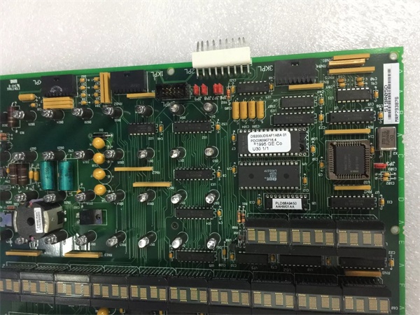
- Functional Acronym: UDSA (Universal Digital Excitation System Board)
- Microprocessor: Intel 80196 16-bit microcontroller
- Memory: Multiple EPROM modules for firmware storage
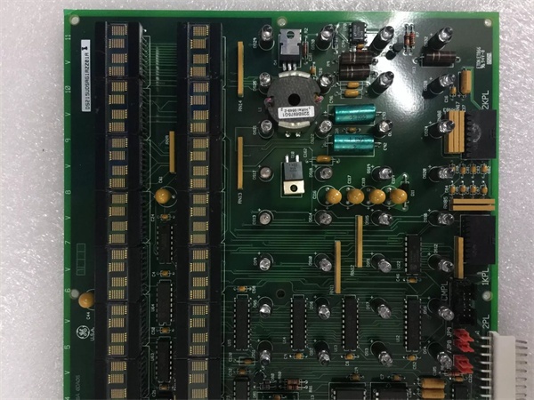
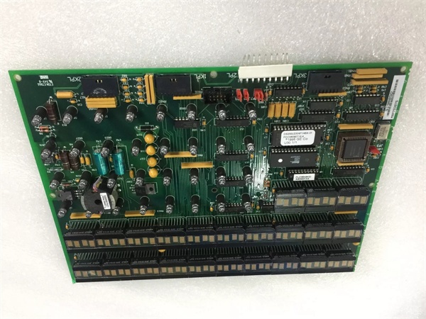
- Display System: 21 × 4-character alphanumeric displays (dot matrix)
- Status Indicators: 32 LEDs for board status and fault indication
- Input Signals: Generator voltage, generator current, field current, rotor speed
- Output Signals: Field voltage command, field current reference
- Protection Functions: Overvoltage, overcurrent, undercurrent, field overexcitation, underexcitation limiters
- Communication Interface: 40-pin connector for board-to-board communication
- Operating Voltage: 24 V DC (exciter power supply)
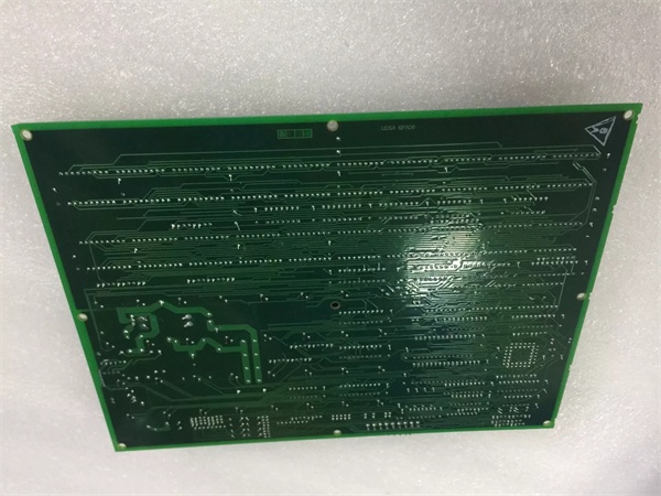
- Board Dimensions: 8.5 × 11 inches (215.9 × 279.4 mm)
- PCB Coating: Normal coating (non-conformal)
- Environmental Requirement: Well-ventilated, clean, dust-free environment
- Capacitor Discharge Time: 30 seconds minimum before handling after power-off
- Functional Revision 1: A
- Functional Revision 2: D (downward compatible enhancement)
- Artwork Revision: E
- Instruction Manual: GEH-6153 (Mark V Turbine Control Manual)
- Safety Standard: IEC 60947-5-1 compliance

GE DS200UDSAG1A
The Real-World Problem It Solves
Synchronous generators need precise field current control to maintain stable output voltage under varying load conditions. The DS200UDSAG1ADE (Excitation Board, Revision D) solves the problem of generator voltage regulation by using an 80196 microprocessor to process voltage and current feedback signals, then adjusting field current output to maintain constant generator terminal voltage regardless of load changes. This board handles the real-time control loop that keeps power generation stable, while simultaneously monitoring for dangerous conditions like overexcitation, underexcitation, and field ground faults. The Revision D update introduces enhanced protection logic and improved downward compatibility with earlier Revision A boards, allowing field upgrades without replacing the entire excitation system. Without this dedicated excitation control, generator output would fluctuate with load swings, potentially causing voltage sags that trip breakers or overvoltage that damages insulation and connected equipment.
Where you’ll typically find it:
- Mark V turbine control cabinets in gas, steam, and combined-cycle power plants
- EX2000 digital excitation systems for synchronous generators
- Generator excitation panels in utility-scale power generation facilities
- Behind drive control cards in Mark V rack assemblies, facing forward for operator access
- Retrofit installations replacing earlier Revision A boards for enhanced functionality
Bottom line: Enhanced microprocessor-based field current regulator—Revision D provides improved protection logic and downward compatibility while maintaining stable generator output voltage through closed-loop control with real-time diagnostics.
Hardware Architecture & Under-the-Hood Logic
The DS200UDSAG1ADE is an intelligent excitation control board built around an Intel 80196 16-bit microprocessor that executes the excitation control algorithm with Revision D functional enhancements. The board receives analog feedback signals from potential transformers (PTs) for generator voltage and current transformers (CTs) for generator and field current, digitizes these signals, and compares the measured voltage against a setpoint reference. The 80196 processor runs a PID control loop that calculates the required field current adjustment to maintain constant terminal voltage, then outputs a field voltage command to the power amplifier (typically a thyristor bridge) that actually drives the generator rotor field. Multiple EPROM modules store the firmware and control parameters, including excitation setpoints, protection limits, and alarm thresholds—Revision D firmware includes enhanced underexcitation limiter logic and improved fault detection algorithms compared to Revision A. The 21 × 4-character displays show real-time values such as terminal voltage, field current, and exciter status, while the 32 LEDs indicate board health, fault conditions, and operational modes. The 40-pin connector provides the data path to other Mark V boards and the operator interface, enabling setpoint adjustments and alarm reporting. Internal capacitors store high-voltage charge for stable operation during transient conditions, which is why the 30-second discharge wait time is mandatory before servicing. The Revision D functional update maintains downward compatibility with Revision A installations, meaning existing setpoints and configurations typically transfer without modification, but introduces new protection features that may require parameter adjustments for optimal performance.
Signal flow:
- Generator output voltage measured by potential transformers (PTs)
- Generator output current measured by current transformers (CTs)
- Field current measured via shunt or CT in excitation circuit
- Analog signals conditioned and digitized by A/D converters
- Digitized values input to 80196 microprocessor
- Microprocessor compares measured voltage to setpoint reference
- PID control loop calculates required field current adjustment
- Field current command output via D/A converters
- Control signal transmitted to power amplifier (thyristor bridge)
- Thyristor bridge adjusts DC field voltage to generator rotor
- Rotor field current changes, affecting generator magnetic field
- Generator terminal voltage adjusted toward setpoint
- Revision D protection logic monitors for overvoltage, overcurrent, underexcitation, enhanced fault detection
- Fault conditions trigger enhanced protection actions and alarms
- Status information displayed on 4-character displays
- LED indicators show board health and operational mode
- Data communicated to other Mark V boards via 40-pin connector
- Operator interface allows setpoint adjustments and diagnostics
GE DS200UDSAG1A
Field Service Pitfalls: What Rookies Get Wrong
Assuming Revision D is a drop-in replacement without parameter checksSwapping Revision D boards without verifying protection setpoints. I’ve seen technicians dropping Revision D boards into systems configured for Revision A, then wondering why underexcitation limiters trip earlier than expected.
- Field Rule: Compare all protection setpoints between old and new boards before commissioning. Revision D has enhanced protection algorithms—verify underexcitation, overexcitation, and V/Hz limits match your generator requirements. Don’t assume same values work across revisions.
Not waiting for capacitor discharge before handlingTouching the board immediately after power-off. I’ve seen technicians yanking the board out the second the breaker trips, getting nailed by stored charge in the filter caps that haven’t had time to bleed down.
- Field Rule: Wait 30 seconds minimum after power-off before touching the board. Verify zero voltage with a multimeter on the capacitor terminals. The caps store high-voltage current and discharge slowly—30 seconds is the safe minimum, not a suggestion.
Forgetting to document jumper and switch settingsInstalling replacement boards with default configurations. I’ve seen technicians swapping in new boards without copying the DIP switch positions from the old one, then wondering why the exciter won’t synchronize or trips on overexcitation limits.
- Field Rule: Photograph or write down every jumper and DIP switch position on the original board before removing it. Configure the replacement board identically before installation. Every exciter application has unique settings—defaults will rarely work.
Mixing up Revision D firmware with Revision A EPROMsInstalling old EPROMs on new Revision D boards. I’ve seen technicians transferring EPROM modules from Revision A boards to Revision D replacements, losing the enhanced protection features and causing control instability.
- Field Rule: Use the EPROM modules that came with the Revision D board unless you’ve verified firmware compatibility. Revision D firmware requires specific EPROM sets—mixing revisions defeats the purpose of the upgrade. If transferring EPROMs, verify part numbers match Revision D requirements.
Ignoring overheating from poor ventilationMounting boards in cramped cabinets with blocked airflow. I’ve seen technicians stuffing replacement boards into cabinets already packed with other heat-generating cards, then complaining about intermittent lockups and premature EPROM failures.
- Field Rule: Verify adequate cabinet ventilation before installation. The 80196 processor and voltage regulators generate significant heat—ensure inlet and outlet vents are clear and cooling fans are functional. If the cabinet is already hot, fix the airflow first or the new board will fail too.
Mishandling ribbon cables on the 40-pin connectorPulling on the cable instead of the connector. I’ve seen technicians ripping ribbon cables out by the wire bundle, tearing conductors and causing intermittent connections that trigger phantom exciter faults.
- Field Rule: Always pull ribbon cable connectors by the plastic housing, never the wires. Support the connector with your other hand to prevent board stress. Label each cable before removal—you don’t want to guess during reinstallation.
Overlooking enhanced LED indicators on Revision DNot checking new LED fault patterns. I’ve seen technicians treating Revision D LED displays the same as Revision A, missing new diagnostic information that Revision D provides for faster fault isolation.
- Field Rule: Study the Revision D LED layout and fault codes before troubleshooting. Revision D has additional diagnostic LEDs that Revision A doesn’t have—consult the updated manual for the new patterns. Don’t rely on Revision A knowledge alone.
Skipping functional testing after Revision D upgradeAssuming the board works because it powers up. I’ve seen technicians installing Revision D boards and immediately returning the unit to service without verifying enhanced protection functions, only to have nuisance trips during normal operation.
- Field Rule: Test all protection functions after Revision D installation. Verify underexcitation and overexcitation limiters trip at correct setpoints, check V/Hz protection, and confirm voltage regulation under load changes. New features require verification—they don’t validate themselves.
Leaving plastic snap holders loose during installationNot securing the board properly in the rack. I’ve seen technicians pushing the board in until the connectors mate but failing to engage the plastic snap holders, causing board vibration and intermittent contact issues that kill the exciter randomly.
- Field Rule: Push the board fully into the rack until all plastic snap holders click into place. Tug gently on the board to verify it’s locked down. Loose boards vibrate themselves to death in turbine cabinets—snap holders matter.
Forgetting to recalibrate after firmware changesNot checking control loop response after Revision D installation. I’ve seen technicians commissioning upgraded boards without verifying PID response, leading to hunting oscillations or sluggish voltage regulation.
- Field Rule: Perform a step response test after Revision D installation. Apply a load change and verify voltage recovers within specification without overshoot or oscillation. Revision D may have different PID tuning parameters—verify the response matches your generator requirements.
Commercial Availability & Pricing Note
Please note: The listed price is for reference only and is not binding. Final pricing and terms are subject to negotiation based on current market conditions and availability. As a critical excitation control component in Mark V turbine control systems, the DS200UDSAG1ADE Revision D board is widely available as refurbished or repaired units. This revision is considered an upgrade from the base Revision A board, offering enhanced protection logic and improved fault detection capabilities while maintaining downward compatibility. When replacing, verify that the EPROM modules are the Revision D firmware version unless you have confirmed compatibility with transferred EPROMs from the original board. The 30-second capacitor discharge requirement must be followed strictly before handling to avoid electric shock and component damage. Due to the safety-critical nature of excitation control, functional testing after installation is mandatory to verify voltage regulation, enhanced protection functions (including underexcitation and overexcitation limiters), and proper communication with other Mark V boards before returning the generator to service. Revision D boards are often preferred over earlier revisions for new installations due to their improved protection features, but ensure your system configuration supports the enhanced capabilities.


